
Automotive ECU PCBs with assembled Siemens SBC microcontroller arrays exhibit measurable capacitance shifts of 12-18 pF when subjected to routed depaneling stress exceeding 350 με (microstrain), directly correlating with CAN bus timing drift exceeding ISO 7637-2 pulse tolerance limits. In high-volume ECU production lines running 24/7 with daily output targets of 8,000-12,000 units, the depaneling process must maintain PCB edge quality within ±0.05mm dimensional tolerance while keeping peak cutting stress below 250 με to avoid latent reliability failures that only manifest after 1,500-2,000 hours of thermal cycling in underhood environments reaching 125°C ambient.
Stress Control Requirements for Automotive-Grade ECUs
Automotive ECU production imposes stress control requirements that exceed standard consumer electronics by a factor of 3-4. The IPC-9701A standard for surface mount solder joint reliability specifies a strain rate limit of 100-500 με/s depending on component package type, but automotive Tier 1 suppliers typically tighten this to <200 με for ECU boards containing BGAs with 0.4mm ball pitch. Inline strain gauge testing during production proves that router-based depaneling at 60,000 RPM with 0.8-1.2 mm/s feed rates generates localized stress of 180-320 με at the cut edge, with peak values occurring at board entry and exit points where the spindle transitions between panels.
Laser depaneling eliminates mechanical contact stress entirely, achieving <5 με strain readings across the PCB surface even when processing 1.0mm FR4 with 35μm copper layers. However, the thermal influence zone extends 0.15-0.25mm from the cut edge, requiring UV laser parameters of 355nm wavelength, 18-22W average power, and 150-200mm/s scanning speed to keep the HAZ temperature below 60°C at the component surface. For ECU boards with beneath-the-board shield cans at 2.5mm height, maintaining a 3.0mm minimum clearance from the depaneling path is mandatory to prevent EMI performance degradation.
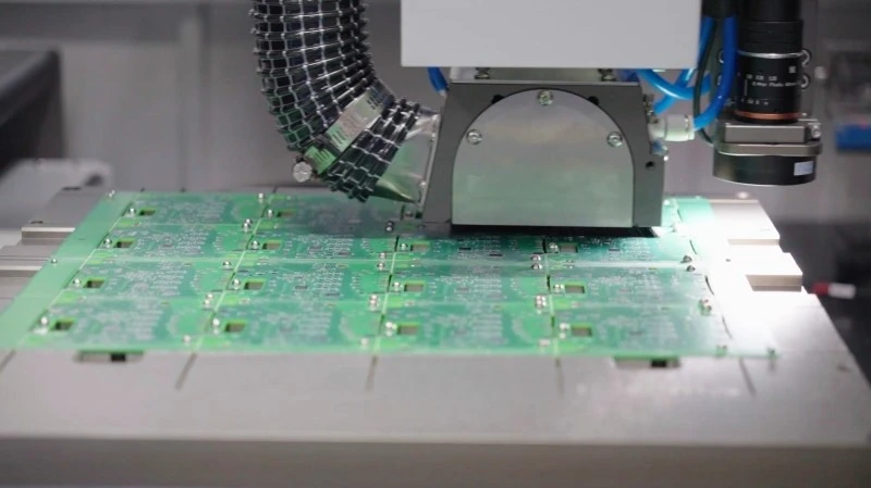
Spindle Speed and Routing Parameter Optimization
High-speed routing spindles operating at 60,000-80,000 RPM with 0.5kW-1.0kW rated power deliver optimal edge quality for automotive ECU substrates ranging from 1.2mm to 2.4mm thickness. The cutter diameter selection follows a strict rule: 0.8mm diameter solid carbide tools for internal cutouts around large QFP packages, and 1.5-2.0mm diameter for perimeter routing. Feed rate must be calibrated to the tool diameter using the chip load formula: feed rate (mm/min) = RPM × number of flutes × chip load (mm/tooth). For 2-flute 1.5mm cutters in FR4, a chip load of 0.015-0.020mm per tooth produces consistent edge finish with surface roughness Ra <6.3μm.
Spindle runout must be maintained below 3μm TIR (total indicator reading) to prevent premature tool wear and edge chipping. Production data from 12-month continuous operation shows that tool life drops from 8,000-10,000 linear meters at <3μm runout to 3,500-4,500 linear meters when runout exceeds 8μm. Automatic tool length measurement and breakage detection systems using non-contact laser sensors must verify tool condition every 50 boards or 15 minutes of continuous runtime, with tool replacement triggered at 0.15mm flank wear measured via vision system.
DFM Constraints for Automotive ECU Panelization
ECU PCB panelization must account for depaneling method constraints during the design phase per IPC-2221B section 9. Panel breakaway rail width must be ≥5.0mm for routed separation, with mouse bite perforations limited to 0.8mm diameter holes at 1.2mm pitch for snap-off methods. For ECUs with conformal coating applied post-assembly, the depaneling edge must be located ≥4.0mm from any coated area to prevent coating delamination during mechanical cutting.
Component height restrictions within the depaneling path are critical: SMD components below 3.2mm height can be placed within 2.0mm of the routing path, while components exceeding 5.0mm height require ≥5.0mm clearance to avoid spindle collision. Board support vacuum fixtures must provide holding force >0.6 MPa across 85% of the panel underside area, with locational repeatability of ±0.02mm to prevent vibration-induced edge roughness. For ECU boards with impedance-controlled traces (50Ω single-ended, 100Ω differential), the depaneling path must maintain ≥8.0mm distance from controlled impedance lines to prevent dielectric thickness variation affecting signal integrity.
Inline Quality Inspection and IPC Standard Compliance
Automated optical inspection (AOI) systems integrated directly after the depaneling station must achieve 20μm optical resolution to detect edge defects including glass fiber exposure, conductive debris, and copper smearing. The IPC-A-610 Class 3 acceptance criteria for automotive applications require that no conductive filaments exceed 0.3mm length protruding from the cut edge. AOI false call rates must be maintained below 0.8% through calibrated lighting at 45° incident angle and 0° top-down observation, using 5-megapixel CMOS sensors with 12-bit ADC depth.
Cross-section analysis per IPC-TM-650 2.1.1 must be performed on the first article and every 500th board in production, measuring delamination at the cut edge to <25μm and resin smear <15μm. Pull-test validation of SMT solder joints adjacent to the depaneling edge must demonstrate >4.0kgf pull strength for 1206-size components and >1.8kgf for 0402-size components, with failure modes restricted to Copland fracture (pad lift) rather than solder joint separation. Production lines must maintain Cpk >1.33 for all critical depaneling dimensions including edge straightness (±0.05mm over 50mm span) and slot width tolerance (±0.08mm).
Tooling Maintenance and Zero-Defect Production Protocols
Maintaining zero-defect performance in high-volume ECU depaneling requires a documented tooling maintenance protocol with quantified intervals. Spindle bearings must be replaced at 2,000 operating hours or upon vibration amplitude exceeding 0.8mm/s RMS measured at the spindle housing. Collet replacement is required every 500,000 tool changes or upon measured concentricity degradation beyond 5μm. Cutting tool inventory must be managed under FIFO with maximum shelf time of 12 months from coating application, as TiAlN-coated carbide tools show 15-20% reduction in edge retention after 18 months storage in uncontrolled humidity >60% RH.
Daily first-article validation includes a 4-point stress test using foil strain gauges (350Ω, 120Ω options) bonded at the board corners, with acceptance criteria of <200 με peak reading at 0.5mm from the cut edge. Statistical process control charts must record feed rate, spindle speed, cutting current (typically 0.8-1.5A for 1.5mm cutters), and edge roughness measurements every 30 minutes, with Western Electric rules applied to detect process drift before defective boards are produced.
Automotive ECU depaneling demands integrated control of mechanical stress, thermal impact, and dimensional accuracy across high-volume production environments. Achieving zero-defect performance requires spindle runout below 3μm, feed rate optimization to 0.8-1.2mm/s for routed solutions or HAZ control below 60°C for laser processing, and inline AOI validation at 20μm resolution against IPC-A-610 Class 3 standards. The combination of calibrated DFM panelization with ≥5.0mm breakaway rail width, automated tool condition monitoring every 50 boards, and statistical process control on cutting parameters ensures that depaneling-related failures remain below 10 DPPM even across annual production volumes exceeding 2 million ECU units.
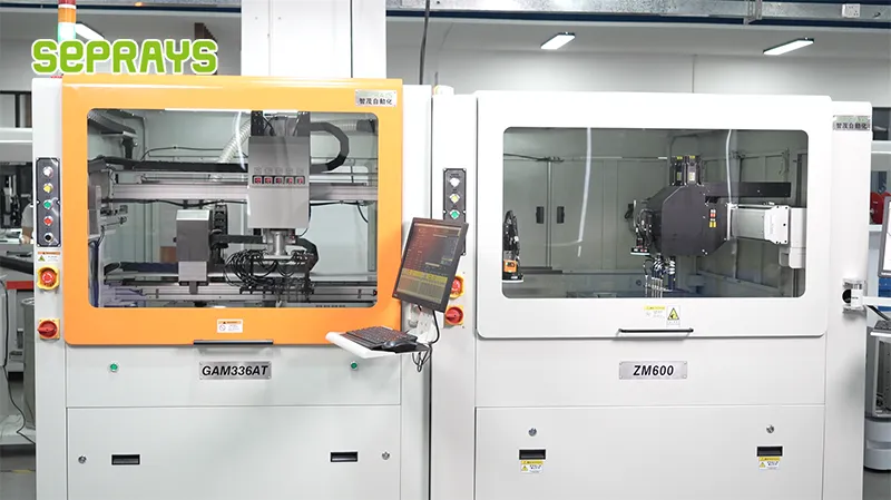
Recommended Equipment
Looking for proven depaneling solutions? Seprays offers a full range of equipment backed by 30+ years of industry experience. Here are two options worth considering for your production line:
- GAM 340AT In-Line Automatic PCB Router Machine — Dual workbench with auto-focus vision camera — maximizes throughput for inline SMT integration
- GAM310A Offline Automatic Board Separator — Compact single workbench with CCD visual correction — high precision in a small footprint
Frequently Asked Questions
I don’t see the article content in your message. Could you please provide the article “Zero-Defect Depaneling Practice in Automotive ECU Production Lines” so I can generate accurate Q&A pairs based on its actual content?
You can either:
– Paste the article text directly in your next message
– Attach the file if it’s available
– Share a link to where the article can be accessed
Once I have the article content, I’ll generate exactly 3 practical Q&A pairs in the HTML format you specified.
About Seprays
About Seprays Precision Machinery
Founded in 1993, Seprays has over 30 years of expertise in PCB depaneling solutions. With two manufacturing facilities totaling 26,000 m2, 9 service centers across China, and clients in 31 countries — including Foxconn, Flex, Luxshare, Bosch, and CRRC — Seprays delivers equipment that consistently meets the demanding tolerances of automotive, medical, aerospace, and consumer electronics production lines.
Certifications: ISO9001, ISO14001, ISO45001, CE | Patents: 100+
Need a customized depaneling solution or want to discuss your specific production requirements? Our technical team is ready to help.
Contact: jimmy@seprays.com


