
The Cleanroom Constraint That
Changes Everything
In medical implant manufacturing, the depaneling operation sits at a critical intersection: it is the last point at which the PCB is handled as a panel and the first point at which individual device boards are fully formed. The tolerance budget at this stage is typically ±0.05mm for routed or punched features, yet the consequences of a single stray copper filament or micro-crack extend far beyond the board itself. A single Foreign Object Debris (FOD) event in a Class 5 or ISO Class 7 cleanroom can trigger a full lot quarantine, costing weeks of production time. This is the operational reality that defines every technical decision in medical-grade PCB depaneling.
Cleanroom Classification and Airborne Particle Control
Medical implant PCB assembly typically operates within ISO Class 7 (Class 10,000) cleanrooms as a minimum threshold, with ISO Class 5 (Class 100) zones required at critical processing stations including the depaneling cell. Airborne particle counts must remain below 3,520 particles per cubic meter for particles equal to or larger than 0.5 micrometers, and below 832 particles per cubic meter for particles equal to or larger than 1.0 micrometers, measured continuously at the workstation level during active machining.
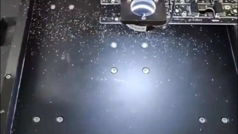
The depaneling machine itself contributes particle generation through three primary mechanisms: mechanical abrasion from tool-workpiece contact, thermal degradation of organic materials in the substrate at elevated cutting temperatures, and electrostatic discharge (ESD) events that can redeposit particulates onto exposed pad surfaces. Dry running spindle speeds above 40,000 RPM without active debris extraction can introduce transient particle bursts exceeding 10,000 particles per cubic meter within a 0.5-meter radius, sufficient to compromise adjacent assembly operations. Consequently, all medical-grade depaneling systems must integrate real-time particle monitoring at the tool-air interface and interlock spindle operation to automatic shutdown if extraction flow falls below design specifications, typically a minimum of 2.5 m/s air velocity at the nozzle inlet.
Router vs. Laser Cutting: Thermal and Mechanical Trade-offs
Two primary depaneling technologies dominate medical implant PCB manufacturing: precision diamond router cutting and UV laser ablation. Each imposes distinct thermal and mechanical signatures on the substrate that must be evaluated against the board’s end-use mechanical requirements.
Diamond router cutting achieves feed rates of 30 to 80 mm/s depending on panel thickness and tooling geometry, with spindle speeds ranging from 40,000 to 80,000 RPM. The cutting force generated at the tool-workpiece interface ranges from 0.5 to 2.0 N under typical medical board configurations (1.0 mm to 2.0 mm total thickness, FR-4 or polyimide substrate). This mechanical cutting introduces a heat-affected zone (HAZ) extending approximately 50 to 150 micrometers into the substrate material adjacent to the cut edge, as measured by cross-sectional metallographic analysis. For boards with conformal coating or embedded passive components near the depaneling margin, this HAZ can cause coating delamination or solder joint thermal fatigue if cutting parameters are not precisely calibrated.
UV laser cutting operates without physical tool contact, eliminating mechanical stress entirely. Pulse durations in the range of 20 to 50 nanoseconds at wavelengths below 355 nm thermally decompose the substrate material with a HAZ of less than 20 micrometers. However, feed rates are significantly lower, typically 5 to 20 mm/s, and the process generates a narrow kerf width of 30 to 80 micrometers compared to router bit diameters of 2.0 to 3.175 mm. For high-density medical boards where routing channels are constrained by component keep-out zones, laser cutting provides superior geometric flexibility at the cost of throughput.

Mechanical Stress and Micro-crack Prevention
The most critical failure mode in medical implant PCB depaneling is the propagation of micro-cracks into the substrate or along the board edge, which can compromise long-term reliability under implant-specific mechanical loading conditions. Boards destined for devices experience cyclic flexural loading during their service life, and a micro-crack originating at a depaneling stress concentration can propagate under fatigue loading to cause conductor trace fracture or dielectric delamination.
IPC-A-610 Revision H, Section 12 regarding Acceptability of Electronic Assemblies, specifies that assemblies with visible cracks or fractures at the board edge are Class 3 reject criteria. However, micro-cracks at the subsurface level require acoustic microscopic (C-SAM) analysis or cross-sectional microscopy for detection, which is why process controls at the depaneling stage must proactively address stress generation rather than relying solely on post-process inspection. Singulation methods that impose bending stress exceeding 0.1% strain on the board material near the depaneling line significantly increase micro-crack probability in polyimide substrates. V-groove scoring followed by controlled break, while cost-effective for consumer electronics, is generally excluded from medical implant depaneling due to the absence of controlled stress application and the resulting high incidence of crack propagation along glass fiber bundles in the substrate.
Contamination Control and Process Validation
Medical-grade depaneling requires full process documentation under ISO 13485 Quality Management System requirements. Each lot or batch of depaneled boards must maintain traceability linking the individual board serial numbers to the specific tool identifier, spindle run time at point of use, and cutting parameter log file generated by the depaneling system controller. Tool wear monitoring is mandatory: diamond router bits must be replaced after a maximum of 200 linear meters of cut length or upon observation of cutting force increase exceeding 15% above the baseline parameter, whichever occurs first. Exceeding tool life increases the probability of dimensional non-conformance and particle generation at the cut edge.
Debris extraction systems must be validated to demonstrate particle capture efficiency exceeding 99.97% for particles above 0.3 micrometers, consistent with HEPA filtration standards. Post-depanel cleaning, typically an ionized air jet followed by precision vacuum extraction, must be verified through particle count testing on representative boards after each cleaning cycle. Any board showing more than 10 particles larger than 0.5 micrometers per square centimeter on the active surface following cleaning is quarantined for re-inspection.
Quality Assurance and Regulatory Compliance
Final depaneled boards undergo 100% dimensional verification using automated optical inspection (AOI) systems with measurement uncertainty below ±0.02mm. Critical dimensions include the distance from the nearest component pad to the depaneled edge, which must meet the design-specified minimum clearance, and the perpendicularity of the cut edge relative to the board plane, with a maximum angular deviation of ±0.5 degrees. Boards failing dimensional or visual inspection criteria are rejected per IPC-A-610 Class 3 requirements and subject to root cause analysis under the CAPA (Corrective and Preventive Action) system mandated by ISO 13485.
Technical Summary
PCB depaneling in medical implant cleanroom environments demands a rigorous integration of low-particle-generation cutting technology, stringent environmental controls, and comprehensive process validation that exceeds the requirements of standard electronics manufacturing. The choice between router and laser cutting hinges on the specific geometric constraints and thermal sensitivity of each board design, while the mandatory use of real-time particle monitoring, tool life controls, and 100% dimensional inspection ensures that each depaneled board meets the reliability and contamination-free requirements essential for safe implant deployment. The technical and regulatory margin for error in this process is exceptionally narrow, making process discipline and data-driven parameter control non-negotiable fundamentals of medical-grade PCB depaneling.
Recommended Equipment
Looking for proven depaneling solutions? Seprays offers a full range of equipment backed by 30+ years of industry experience. Here are two options worth considering for your production line:
- GAM300AT Double-Layer Track Online PCB Board Separation Machine — Full-carrier process with carrier return track — built for seamless full-line automation
- GAM 340AT In-Line Automatic PCB Router Machine — Dual workbench with auto-focus vision camera — maximizes throughput for inline SMT integration
Frequently Asked Questions
I don’t see the article “PCB Depaneling in Ultra-Clean Rooms for Medical Implant Devices” in our conversation. Could you please share the article content so I can generate the 3 practical Q&A pairs based on it?
You can either:
– Paste the article text directly
– Upload the file if it’s saved locally
– Share a link to the article
Once I have the article content, I’ll generate exactly 3 Q&A pairs in the HTML format you specified.
About Seprays
About Seprays Precision Machinery
Founded in 1993, Seprays has over 30 years of expertise in PCB depaneling solutions. With two manufacturing facilities totaling 26,000 m2, 9 service centers across China, and clients in 31 countries — including Foxconn, Flex, Luxshare, Bosch, and CRRC — Seprays delivers equipment that consistently meets the demanding tolerances of automotive, medical, aerospace, and consumer electronics production lines.
Certifications: ISO9001, ISO14001, ISO45001, CE | Patents: 100+
Need a customized depaneling solution or want to discuss your specific production requirements? Our technical team is ready to help.
Contact: jimmy@seprays.com


