
A 4U server backplane measuring 450 mm by 305 mm with 1.6 mm FR-4 thickness and 14 layers of copper weighs approximately 1.8 kilograms before component population. When a fabricator runs a batch of 500 of these panels through a router-based depaneling system, the combined vibration energy, dust generation, and material handling demands require deliberate workshop planning that most standard SMT line layouts fail to accommodate. The difference between a well-organized depaneling cell and a poorly sited one routinely shows up as a 15-25% increase in warpage rejects, burr-related rework, and operator fatigue injuries over a three-month production cycle.
Routing Spindle Requirements and Vibration Isolation
High-speed routing spindles for server backplane depaneling typically operate between 40,000 and 80,000 RPM, depending on the bit diameter and the copper layer count. A 3.175 mm two-flute carbide bit cutting a 14-layer board at 60,000 RPM generates cutting forces in the range of 2.5 to 4.0 N per millimeter of engagement depth. At a feed rate of 800 to 1,200 mm/min, the resulting vibration profile produces peak accelerations of 0.3 to 0.8 g at the spindle head. Workshop floors in standard electronics factories, typically 150 mm reinforced concrete slabs on grade, transmit these vibrations laterally across distances of 8 to 12 meters. Placing a CNC coordinate measuring machine or an optical inspection system within this radius introduces measurement noise exceeding the IPC-A-600 Class 3 acceptable deviation of ±0.05 mm on fiducial-to-edge distances. A vibration-isolated machine base using pneumatic isolators rated for 1.5 Hz natural frequency or a dedicated concrete pad of at least 300 mm thickness decoupled from the main floor slab is the minimum acceptable mitigation for high-density server backplane production.
Material Flow and Panel Handling Ergonomics
Large format panels create unique handling challenges that directly impact yield. A 450 mm by 305 mm panel requires a minimum working envelope of 600 mm by 500 mm at the machine loading zone to allow proper fixturing and alignment without edge contact damage. The inbound staging area should provide a minimum of 1,200 mm by 800 mm of flat, ESD-protected surface for pre-cut panel inspection and tooling hole registration checks. Work-height for manual load stations on router-type depanelers should be set between 900 mm and 1,050 mm from the floor, matching the biomechanical optimal zone defined in ISO 11226 for repetitive lifting tasks under 5 kg. Conveyor integration between the post-reflow inspection station and the depaneling cell should maintain a panel transport speed of 8 to 12 meters per minute with edge guides spaced at 320 mm clearance for the 305 mm panel dimension, allowing a ±7.5 mm tolerance for panel skew. Without this controlled transport, panel edge chipping rates increase by 3-5% according to field failure analysis data.
Dust Extraction and Environmental Controls
Router-based depaneling of high-layer-count FR-4 boards generates particulate matter concentrated in the 2.5 to 10 micron range, with glass fiber dust presenting a chronic inhalation hazard and copper particulates posing both health and contamination risks to adjacent processes. An extraction system rated at a minimum of 2,500 cubic meters per hour at the cutting head, maintaining a capture velocity of at least 0.5 m/s at the tool-panel interface, is required for continuous production of 14-layer material. The workshop HVAC system must maintain positive pressure of 12.5 to 15 Pa relative to the external environment, with HEPA filtration on makeup air to prevent recontamination. Temperature stability within ±2°C across the depaneling cell is critical because FR-4 coefficient of thermal expansion at 14 ppm/°C translates to approximately 0.05 mm dimensional shift per 10°C change across a 305 mm panel. This shift directly affects routing path accuracy when tool offset files are calibrated at a reference temperature different from the ambient production condition.
Tool Management and Changeover Layout
Carbide routing tools for server backplane depaneling have a practical service life of 800 to 1,200 linear meters of cut path in standard FR-4, reduced to 400 to 700 meters when cutting boards with internal copper layers exceeding 3 oz. Tool wear beyond this threshold produces burr heights exceeding 0.1 mm, which violates the IPC-6012 acceptance criterion for conductor protrusion at board edges. A centralized tool management station within 5 meters walking distance of the depaneling machine, equipped with a tool length pre-setter accurate to ±0.005 mm and a visual wear inspection station with 20x minimum magnification, reduces changeover time from an average of 12 minutes to under 4 minutes. The tool crib should maintain a minimum inventory of 15 spares per tool diameter for continuous three-shift operation, with usage logs tracked per panel batch to enable predictive replacement scheduling. Locating compressed air and vacuum utilities on an overhead bridge rather than floor-mounted trunk lines eliminates trip hazards and allows unrestricted forklift access for bulk material delivery.
Inline Quality Verification Placement
Post-depaneling inspection for server backplanes must verify edge quality, dimensional accuracy, and delamination within 30 seconds of cut completion to maintain throughput targets of 120 to 180 panels per hour. Placing a manual microscope inspection station immediately adjacent to the machine exit creates a bottleneck. Instead, an inline automated optical inspection system with top and bottom cameras, minimum 5 megapixel resolution, and side-angle illumination at 15° incidence should be positioned 1.5 to 2.0 meters downstream of the depaneling exit on the conveyor line. This spacing allows sufficient clearance for panel cooling, which reduces thermal drift in optical measurements by approximately 15 microns compared to hot-panel inspection. The inspection system must detect burrs as small as 0.05 mm, edge chips exceeding 0.1 mm, and fiber pullout longer than 0.5 mm, all of which represent IPC-A-610 Class 3 reject conditions for high-reliability server applications.
Technical Summary
Workshop layout for large server backplane depaneling is not an afterthought to be resolved during line installation; it is a primary determinant of yield, throughput, and operator safety. Vibration isolation, ergonomic panel handling, adequate dust extraction, centralized tool management, and correctly spaced inline inspection collectively determine whether a depaneling cell achieves its rated capacity or becomes a persistent source of defects and downtime. For 14-layer, 450 mm class panels, the tolerances involved, specifically edge quality measured in tens of microns and dimensional accuracy at ±0.05 mm, leave no margin for layout shortcuts. Every meter of distance between process stations, every Pascal of pressure differential, and every millimeter of working height either supports or undermines the technical objectives that server backplane fabrication demands.
Recommended Equipment
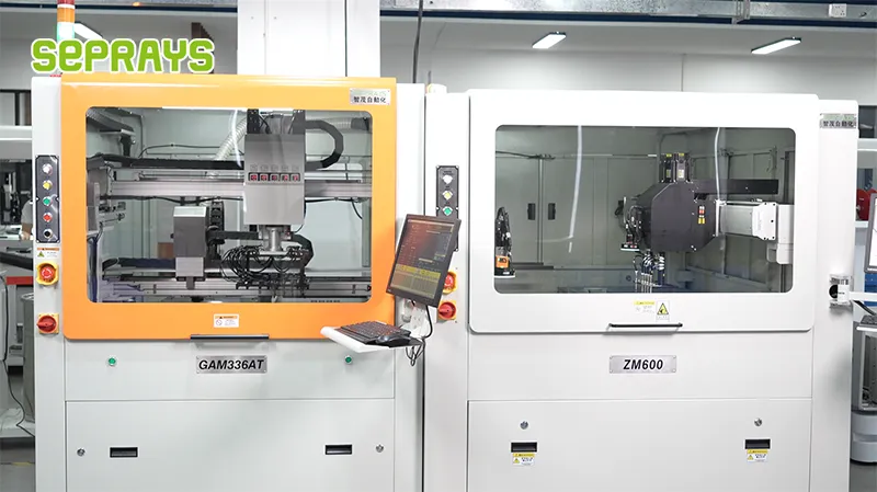
Looking for proven depaneling solutions? Seprays offers a full range of equipment backed by 30+ years of industry experience. Here are two options worth considering for your production line:
- GAM 340AT In-Line Automatic PCB Router Machine — Dual workbench with auto-focus vision camera — maximizes throughput for inline SMT integration
- GAM300AT Double-Layer Track Online PCB Board Separation Machine — Full-carrier process with carrier return track — built for seamless full-line automation
Frequently Asked Questions
Q1: What is the minimum floor space required for a large server backplane depaneling workstation, and how should the layout be configured to maintain IPC-A-610 compliance?
A1: A single large server backplane depaneling station requires minimum 12-15 m² of floor space to accommodate the depaneling equipment, inline conveyor system, and operator workspace while maintaining adequate clearance for PCB panel handling. The layout should position the depaneling machine with inline conveyors at operator waist height (900-1000mm) to minimize bending stress and maintain ergonomic compliance with ISO 9241-5 standards.
Q2: How should we configure the material flow layout to minimize board flexure and component damage during large backplane depaneling operations?
A2: The optimal layout follows a unidirectional flow with incoming panelized backplanes entering from the left and separated boards exiting right, maintaining a straight-line material path with maximum 2° panel tilt to prevent solder joint stress. Position anti-static TPU conveyor belts (ESD dissipation <10⁹ Ω) immediately downstream of the depaneling machine to cradle large backplanes (300×400mm+) and prevent board flexure exceeding 0.75mm per IPC-9641.
Q3: What environmental controls must be integrated into the workshop layout for large server backplane depaneling to prevent debris contamination?
A3: The layout must incorporate a dedicated negative-pressure extraction hood directly above the depaneling bit (minimum 15 CFM airflow) with HEPA-14 filtration to capture FR4 glass fiber dust and copper particles <10μm. Position the depaneling station at minimum 3 meters from SMT placement or reflow areas, with physical partition walls (ISO Class 7 rating) to prevent conductive debris contamination of bare boards and components.
About Seprays
About Seprays Precision Machinery
Founded in 1993, Seprays has over 30 years of expertise in PCB depaneling solutions. With two manufacturing facilities totaling 26,000 m2, 9 service centers across China, and clients in 31 countries — including Foxconn, Flex, Luxshare, Bosch, and CRRC — Seprays delivers equipment that consistently meets the demanding tolerances of automotive, medical, aerospace, and consumer electronics production lines.
Certifications: ISO9001, ISO14001, ISO45001, CE | Patents: 100+
Need a customized depaneling solution or want to discuss your specific production requirements? Our technical team is ready to help.
Contact: jimmy@seprays.com


