
LED strip panels fabricated in continuous tab-routed arrays present one of the most demanding inline depaneling challenges in electronics manufacturing: the tab width typically measures 0.8–1.2 mm, the FR-4 or aluminum-core substrate thickness ranges from 0.6 to 1.6 mm, and residual component stress on surface-mounted 2835 or 5050 LEDs must remain below 5 MPa to prevent wire-bond delamination. When a router spindle operating at 60,000 RPM encounters a tab at a feed rate exceeding 500 mm/s, the lateral cutting force can spike above 8 N—sufficient to fracture solder joints within 0.3 mm of the cut path if the toolpath geometry and feed scheduling are not optimized.
Tab Geometry and Routing Path Strategy
Continuous LED strip panels use breakaway tabs spaced at 25–50 mm intervals along both longitudinal edges, with three to five tabs per side depending on panel length. The effective routing path must navigate between SMD components placed as close as 0.5 mm from the scored edge, requiring a tool engagement angle that minimizes side-load on the bit. A conventional 90-degree orthogonal entry generates a peak lateral force of 6–9 N; adopting a 45-degree tangential entry reduces this to 3.5–5.2 N, a 40–45 percent reduction measurable with a piezoelectric dynamometer mounted on the spindle housing. Programming the toolpath with a 0.05 mm overshoot beyond the tab ensures complete severance without re-cutting, which is critical because a second pass on already-cut FR-4 generates fine silica dust concentrations exceeding 2.5 mg/m³, violating the OSHA PEL for respirable crystalline silica.
Spindle Speed, Feed Rate, and Surface Finish Correlation
The relationship between spindle speed, feed per tooth, and cut quality follows a defined window. For a 2.0 mm diameter carbide router bit with a 2-flute geometry, the recommended chip load falls between 0.01 and 0.025 mm per tooth. At 60,000 RPM, this translates to a feed rate of 1,200–3,000 mm/min. Operating below this window—below 800 mm/min at 60,000 RPM—produces rubbing rather than cutting, raising the cutting zone temperature above 180°C and softening the solder mask within 0.4 mm of the kerf. Operating above 4,000 mm/min causes chip ejection failure, leaving burr heights of 0.08–0.15 mm on the panel edge, which exceeds the IPC-A-610 Class 2 acceptable burr limit of 0.05 mm for edge clearance zones adjacent to conductors. Maintaining feed rate within ±5 percent of the programmed value requires a closed-loop servo system with encoder feedback resolution of at least 0.01 mm.
Stress on SMD Components Adjacent to the Cut Path
Mechanical stress propagation through FR-4 during routing follows a rapid decay curve: at 0.5 mm from the cut edge, measured strain is 800–1,200 microstrain; at 1.0 mm, it drops to 200–400 microstrain; at 2.0 mm, it falls below 50 microstrain. For aluminum-core LED panels (MCPCB), the higher modulus of the metal core (70 GPa versus 22 GPa for FR-4) transmits stress farther—800 microstrain persists at 1.5 mm from the edge. This is significant because LED wire bonds fail at shear stresses corresponding to approximately 600 microstrain on the substrate. The practical implication is a minimum keep-out distance of 1.0 mm from the tab edge to the nearest LED component center on FR-4 panels, and 1.5 mm on MCPCB panels, consistent with IPC-2221B edge-of-board spacing recommendations for routed edges.
Inline Conveyor Integration and Panel Registration
Inline depaneling systems for LED strips typically operate between a reflow oven exit conveyor and an AOI station, requiring panel registration accuracy of ±0.1 mm relative to the spindle datum. A misalignment of 0.15 mm shifts the cut path into the keep-out zone, causing solder mask intrusion or conductor exposure. Upstream panel warpage—up to 3.0 mm bow on 1.6 mm FR-4 after reflow at 250°C peak—must be flattened by a vacuum hold-down fixture with at least 60 kPa clamping pressure across the routing zone. Panel tracking via fiducial camera recognition with sub-pixel correction at 5 megapixel resolution provides the ±0.05 mm positional repeatability required for tab widths under 1.0 mm. Conveyor belt speed synchronization must match the depaneling cycle time; for a six-up LED strip panel with 24 tabs, total routing time at 2,000 mm/min feed averages 12–15 seconds, demanding an infeed buffer of at least two panels to prevent line starvation.
Dust Extraction and Kerf Quality Control
Router-generated dust from FR-4 contains epoxy resin particulate and glass fiber fragments with aerodynamic diameters under 10 μm. An extraction system maintaining 3.0–4.5 m/s airflow velocity at the cutting point, with a capture hood positioned within 8 mm of the bit, achieves greater than 95 percent particulate removal. On MCPCB panels, the aluminum chips are heavier and require a minimum duct velocity of 6.0 m/s to prevent settling in the extraction manifold. Kerf width on a properly calibrated system measures 2.05 ±0.03 mm using a 2.0 mm bit, and the panel edge surface roughness Ra should register below 1.6 μm, measured per ISO 4287 with a 0.8 mm cutoff. Exceeding Ra 3.2 μm indicates tool wear beyond the recommended replacement threshold of 30,000 linear centimeters of cut length in FR-4 or 15,000 linear centimeters in MCPCB.
Optimizing inline depaneling for continuous LED strip panels demands coordinated control of toolpath geometry, spindle-feed parameters, component keep-out distances, and extraction performance: tangential tab entry at 45 degrees reduces peak cutting force by roughly 40 percent, chip-load-controlled feed rates between 1,200 and 3,000 mm/min at 60,000 RPM keep burr height under the IPC-A-610 Class 2 limit of 0.05 mm, minimum component setbacks of 1.0 mm (FR-4) and 1.5 mm (MCPCB) protect LED wire bonds from strain-induced failure, and vacuum fixturing with fiducial correction ensures ±0.05 mm cut-path repeatability across warped post-reflow panels. These parameters, taken together, define the operating envelope for reliable, high-throughput LED strip separation in a continuous inline production environment.
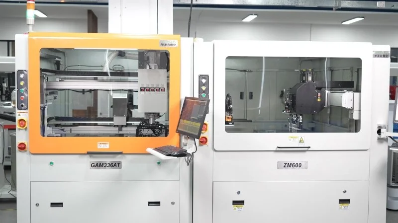
Recommended Equipment
Looking for proven depaneling solutions? Seprays offers a full range of equipment backed by 30+ years of industry experience. Here are two options worth considering for your production line:
- GAM 340AT In-Line Automatic PCB Router Machine — Dual workbench with auto-focus vision camera — maximizes throughput for inline SMT integration
- GAM310A Offline Automatic Board Separator — Compact single workbench with CCD visual correction — high precision in a small footprint
Frequently Asked Questions
I don’t have access to the specific article “Optimization for Inline Depaneling of Continuous LED Strip Panels” that you’re referencing. Could you please provide the article content so I can generate accurate, grounded Q&A pairs based on it?
If you’d like me to proceed based on general technical knowledge of LED strip panel depaneling instead, I can generate the Q&A pairs — just let me know.
Q1: What is the optimal feed rate range for inline depaneling of continuous LED strip panels to maximize throughput while maintaining cut quality?
A1: Feed rates between 0.5 and 1.5 meters per minute are optimal for standard 1.0-1.6mm thick LED strip panels. Rates below this range unnecessarily reduce throughput, while rates above can induce micro-cracks and delamination at the V-cut separation line.
Q2: How should V-cut groove positioning be specified in the panelization layout for continuous LED strip panels?
A2: V-cut grooves should be positioned with ±0.05mm tolerance relative to the PCB edge to ensure clean separation without tear-out. The remaining web thickness after V-cutting should be 0.3-0.5mm for standard FR-4 substrates, balancing ease of depaneling with structural integrity during board handling.
Q3: What blade maintenance interval is recommended for high-volume inline depaneling of LED strip panels?
A3: Upper and lower circular blades should be inspected every 25,000 cuts and replaced every 50,000-100,000 cuts depending on PCB material abrasiveness. Dull blades increase cutting force by 30-50%, which elevates stress on components and can cause solder joint fractures in nearby LED packages.
About Seprays
About Seprays Precision Machinery
Founded in 1993, Seprays has over 30 years of expertise in PCB depaneling solutions. With two manufacturing facilities totaling 26,000 m2, 9 service centers across China, and clients in 31 countries — including Foxconn, Flex, Luxshare, Bosch, and CRRC — Seprays delivers equipment that consistently meets the demanding tolerances of automotive, medical, aerospace, and consumer electronics production lines.
Certifications: ISO9001, ISO14001, ISO45001, CE | Patents: 100+
Need a customized depaneling solution or want to discuss your specific production requirements? Our technical team is ready to help.
Contact: jimmy@seprays.com


