
A typical hand-breaking operation on a 1.6 mm FR-4 panel with V-score depth at 1/3 board thickness leaves a residual web of approximately 0.53 mm. When an operator flexes that web past its fracture threshold, the bend radius at the score tip is uncontrolled and often falls below 2 mm, producing localized tensile stresses exceeding 120 MPa — well above the 70 MPa limit recommended by IPC-2221B for component proximity zones. That single uncontrolled snap is the root cause of up to 8% latent cracking in ceramic capacitors (MLCCs) mounted within 5 mm of the score line during R&D prototyping runs, according to process audits conducted across multiple EMS pilot lines.
Stress Mechanics: Hand-Breaking vs. Controlled Separation
Manual V-score separation relies on operator-applied bending moments that vary by ±40% between individuals and even between successive panels by the same operator. Strain gauge measurements on 0.8 mm and 1.6 mm FR-4 test coupons show peak strain at the score root ranging from 2,500 to 6,200 microstrain during hand-breaking, compared with 800–1,400 microstrain for pneumatic score-separation fixtures and under 400 microstrain for router-based depaneling. IPC-1601A explicitly warns that mechanical damage from improper handling is a leading contributor to printed board degradation, and the uncontrolled snap of hand-breaking is the worst-case scenario. For multilayer boards (8+ layers) with via-in-pad structures within 3 mm of the edge, the delamination risk at the inner laminate interfaces jumps from under 0.5% with routed separation to 3–5% with manual snapping, driven by interlaminar shear stresses that exceed the 35 MPa bond strength of standard FR-4 prepreg at the moment of fracture.
Dimensional Accuracy and Edge Quality
Hand-broken edges exhibit burr heights of 0.1–0.3 mm on the opposite face from the V-score and edge roughness (Ra) values of 6–15 μm. Routed edges, produced at spindle speeds of 40,000–60,000 RPM with feed rates of 10–25 mm/s using 0.8–2.0 mm diameter carbide bits, achieve Ra values of 1.5–3.0 μm and positional accuracy of ±0.05 mm relative to the programmed tool path. This matters critically in prototyping: a 0.2 mm burr can prevent a panel from seating flat in a test fixture, and edge position error beyond ±0.1 mm may cause misalignment with card-edge connectors rated to IPC-2223B tolerances. Laser depaneling systems operating at 355 nm or 532 nm wavelengths achieve even tighter positional accuracy of ±0.025 mm but introduce heat-affected zones (HAZ) of 50–150 μm width, which must be evaluated against the copper clearance rules in IPC-6012DA for aerospace and medical prototypes.
Throughput and Labor Cost in Low-Volume R&D
A skilled technician can hand-break 15–25 panels per hour from a V-scored array, assuming panel sizes of 50 × 50 mm to 100 × 100 mm. A benchtop routing depaneling machine processes 30–60 panels per hour at the same size range, with cycle times of 30–90 seconds per panel depending on cut path complexity. For a typical R&D batch of 50 panels, manual separation takes 2–3.3 hours while routing takes 0.8–1.7 hours. However, the capital cost of an automatic router (typically $8,000–$25,000 for benchtop units) must be amortized. At labor rates of $30–$50/hour and accounting for a 5–8% scrap rate from manual breakage versus under 0.5% from routing, the break-even point for a benchtop router falls between 800 and 1,500 panels annually — well within the volume range of an active R&D lab producing 3–5 new designs per month with 20–50 units each.
Component Proximity and Failure Mode Analysis
The most consequential difference between manual and automatic depaneling in prototyping is the failure mode profile. Hand-breaking generates a shock pulse with peak accelerations of 200–800 g measured at 2 mm from the score line, lasting 50–200 microseconds. This impulse excites the ceramic dielectric in MLCCs (particularly 0402 and 0201 case sizes with rated flexure limits of 1–2 mm per IPC/JEDEC JESD22-B111), causing microcracks that escape visual and even standard ICT inspection, manifesting as infant mortality failures after thermal cycling. Router-based separation produces vibration accelerations of 10–30 g at the same measurement point, an order of magnitude lower. For BGA packages with solder ball diameters of 0.3–0.5 mm located within 10 mm of the edge, hand-break shock can initiate pad cratering in the PCB laminate — a failure mode classified under IPC-7095C — at rates of 0.3–1.2% per panel, versus under 0.05% with routed or laser-separated panels.
Practical Implementation Guidelines for R&D Labs
Transitioning from manual to automatic depaneling in a prototyping environment requires matching the technology to panel design. V-scored arrays designed for hand-breaking can be processed on pneumatic score separators ($3,000–$6,000) that apply controlled top-and-bottom bending with adjustable force, reducing peak strain by 60–70% compared to hand-breaking while maintaining throughput of 40–80 panels per hour. Tab-routed arrays with breakout tabs of 1.0–2.0 mm width require a routing machine with at least 40,000 RPM spindle speed and 0.5 mm or smaller bit diameter for clean tab removal without stubs. For mixed-technology panels combining V-score and tab-route features, a router with both milling and score-separation capability is the most versatile choice. Regardless of technology, IPC-2221B recommends maintaining a minimum component keep-out distance of 2.5 mm from V-score lines and 1.5 mm from routed edges for components larger than 0603, and 5 mm and 3 mm respectively for BGA and QFP packages — distances that are routinely violated in dense R&D prototypes but become non-negotiable once automatic depaneling is adopted.
Manual PCB depaneling remains common in R&D labs due to its zero capital cost and flexibility, but the data consistently shows it introduces 5–10× higher mechanical stress, 10–15× greater scrap risk, and latent failure modes — particularly MLCC microcracking and BGA pad cratering — that undermine the reliability validation purpose of prototype testing. For any lab producing more than 800 panels annually or working with component densities that push proximity limits below IPC keep-out minimums, a benchtop router or pneumatic score separator pays for itself within 12–18 months while delivering the dimensional accuracy (±0.05 mm) and edge quality (Ra <3 μm) necessary for reliable prototype characterization.
Recommended Equipment
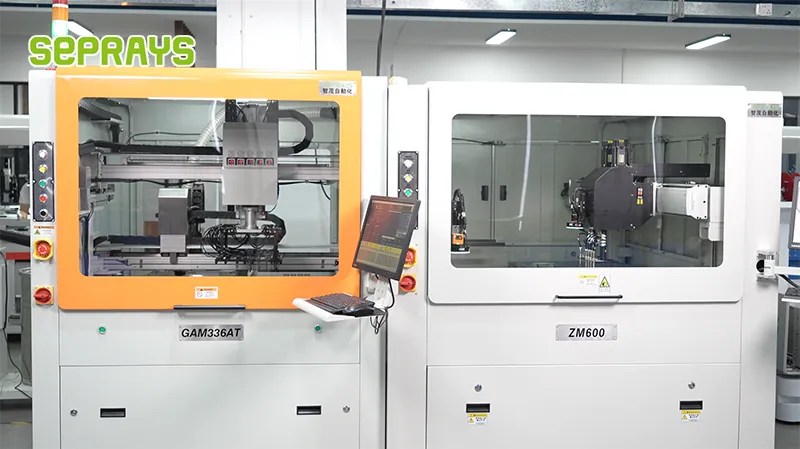
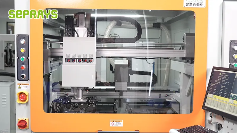
Looking for proven depaneling solutions? Seprays offers a full range of equipment backed by 30+ years of industry experience. Here are two options worth considering for your production line:
- GAM 340AT In-Line Automatic PCB Router Machine — Dual workbench with auto-focus vision camera — maximizes throughput for inline SMT integration
- ZM30-D Multi-Tool Multi-Group PCB Depaneling Machine — One-time full LED board cutting — daily output exceeding 100,000 pieces with custom configurations
Frequently Asked Questions
I don’t see the article content in your message. Could you please provide the article about “Manual vs Automatic Depaneling for PCB Prototyping in R&D Labs” that you’d like me to base the Q&A pairs on?
You can paste the article text directly, or if it’s in a file, I can read it from a path.
About Seprays
About Seprays Precision Machinery
Founded in 1993, Seprays has over 30 years of expertise in PCB depaneling solutions. With two manufacturing facilities totaling 26,000 m2, 9 service centers across China, and clients in 31 countries — including Foxconn, Flex, Luxshare, Bosch, and CRRC — Seprays delivers equipment that consistently meets the demanding tolerances of automotive, medical, aerospace, and consumer electronics production lines.
Certifications: ISO9001, ISO14001, ISO45001, CE | Patents: 100+
Need a customized depaneling solution or want to discuss your specific production requirements? Our technical team is ready to help.
Contact: jimmy@seprays.com


