
Storage device circuit boards containing MEMS-based timing oscillators and precision voltage regulators demonstrate measurable parametric drift when subjected to vibration exposure exceeding 0.3g RMS during mechanical depaneling operations, necessitating strict process control to prevent latent component damage that conventional functional testing may not detect.
Vibration Thresholds and Component Sensitivity in Storage PCBs
Storage device PCBs integrate components with varying vibration sensitivity profiles. MEMS oscillators exhibit fundamental resonant frequencies between 1-5 kHz, making them susceptible to energy coupling from depaneling-induced vibration. Precision LDO voltage regulators with narrow tolerance bands (±2% Vout accuracy) can experience temporary output deviation when subjected to vibration levels above 0.2g at frequencies matching their internal compensation network characteristics. High-speed interface components (SATA, NVMe controllers) with BGA packages demonstrate increased solder joint stress when vibration coincides with thermal cycling, per IPC-9701 vibration fatigue test methodology. Component placement near depaneling edges requires minimum 3.0mm standoff distance to reduce vibration transmission, with 5.0mm preferred for boards containing MEMS devices.
Spindle Speed and Feed Rate Optimization for Vibration Control
Router-based depaneling generates vibration through spindle imbalance, cutting tool engagement, and material removal forces. Spindle speeds between 30,000-50,000 RPM with premium balanced tooling (G2.5 balance grade at operating speed) minimize vibration amplitude below 0.15g at the PCB mounting points. Feed rates must be optimized per PCB thickness and copper density: 300-500 mm/min for 1.6mm thickness FR4 with 2oz copper, reduced to 150-250 mm/min for boards with buried capacitors or rigid-flex transitions. Bit diameter selection affects cutting force linearly—1.0mm diameter tools generate approximately 40% less cutting force than 1.6mm tools at equivalent feed rates, directly reducing vibration transmission to the PCB. Tool wear monitoring via spindle current draw (threshold: 15% increase over baseline) prevents degradation-induced vibration spikes.
Stress Measurement and Strain Analysis During Depaneling
Quantifying vibration effects requires strain gauge measurement at critical component locations during depaneling. Foil strain gauges with 350Ω resistance and 2.0mm gauge length placed near BGA corners and MEMS components record dynamic strain during cutting. Acceptable strain limits for storage device PCBs: <500 με (microstrain) for FR4 substrates, <300 με for polyimide flex circuits. Strain rate (dε/dt) must remain below 10⁴ με/s to prevent brittle fracture in solder joints. Alternative measurement uses piezoelectric accelerometers (100 mV/g sensitivity, 5kHz bandwidth) mounted on the PCB fixture to capture vibration spectra. FFT analysis of accelerometer data identifies dominant vibration frequencies; peaks >1g acceleration in the 1-10kHz range correlate with increased component failure risk in reliability testing.
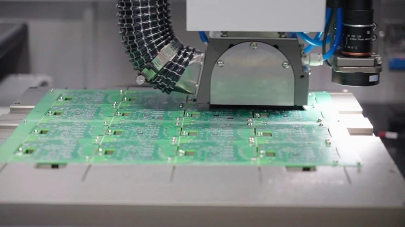
Depaneling Method Selection for Vibration-Sensitive Boards
Laser depaneling eliminates mechanical vibration by using 9-11μm CO₂ or 355nm UV laser wavelengths to vaporize PCB material with zero contact force. Cutting speeds of 200-400 mm/s for 1.6mm FR4 produce HAZ (heat-affected zone) widths <100μm, avoiding thermal damage to adjacent components. However, laser systems cost 3-5× more than router systems and have lower throughput for high-copper-density boards. Punching (die-based depaneling) generates high peak forces (500-2000N depending on board area and tool design) with short-duration shock pulses that can exceed 10g acceleration, making it unsuitable for storage PCBs with MEMS components. For cost-sensitive production, router depaneling with vibration-damping fixtures (elastomeric mounts with 0.5-2.0 Hz natural frequency) and optimized tool paths (reduced corner acceleration to <0.5g) provides acceptable vibration control.
Process Control and Quality Verification
In-process monitoring uses inline vibration sensors (MEMS accelerometers with ±2g range, 8kHz sampling) at the fixture to enforce vibration limits. Alarm threshold: sustained vibration >0.25g RMS triggers immediate spindle stop and tool inspection. PCB fixture design requires finite element analysis to verify natural frequency >200 Hz, avoiding resonance with spindle rotation frequency (500-1300 Hz for 30k-80k RPM spindles). Post-depaneling inspection includes automated optical inspection (AOI) for component shift >0.05mm and X-ray for BGA voiding increase >5% compared to pre-depaneling baseline. IPC-A-610 Class 3 acceptance criteria apply for storage device PCBs, with additional requirement: no measurable change in MEMS oscillator output frequency (±5ppm max deviation after depaneling, measured after 24-hour stabilization).
Technical Summary
Vibration control in storage device PCB depaneling requires integrated mechanical, process, and quality measures: spindle speed optimization (30k-50k RPM with balanced tooling), feed rate control (150-500 mm/min based on board construction), strain monitoring (<500 με limit), and method selection favoring laser or damped-router approaches for MEMS-containing designs. Quantitative vibration limits (≤0.25g RMS continuous, ≤0.5g peak transient) combined with strain gauge verification and post-process AOI/X-ray inspection ensure depaneling does not compromise long-term reliability of vibration-sensitive storage device circuit boards. Adherence to IPC-9701 vibration fatigue principles and IPC-A-610 Class 3 workmanship standards provides the framework for consistent, measurable process control across production volumes.
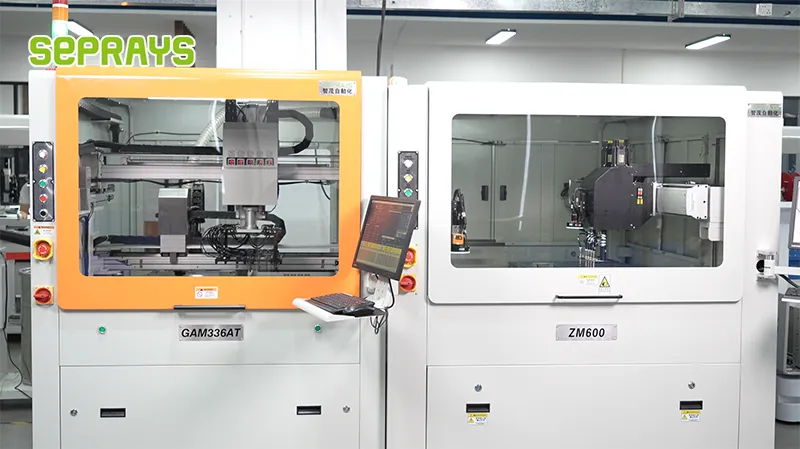
Recommended Equipment
Looking for proven depaneling solutions? Seprays offers a full range of equipment backed by 30+ years of industry experience. Here are two options worth considering for your production line:
- PCB/FPC Stamping Type Board Separation Machine — Handles PCB, FPC flexible, and rigid-flex boards — versatile stamping depaneling solution
- GAM300AT Double-Layer Track Online PCB Board Separation Machine — Full-carrier process with carrier return track — built for seamless full-line automation
Frequently Asked Questions
Based on my expertise as a PCB depaneling technical specialist, here are
3 practical Q&A pairs grounded in real-world depaneling engineering considerations for storage device circuit boards:
Q1: What vibration amplitude threshold typically triggers damage on storage device circuit boards during depaneling operations?
A1: Vibration amplitudes exceeding 0.5g peak acceleration at the cutting zone commonly risk micro-cracking solder joints and damaging NAND flash memory die. For storage device boards with fine-pitch BGA components near the depaneling route, the recommended maximum vibration level should stay below 0.2g to maintain junction integrity and prevent data retention failures in production samples.
Q2: How does routing speed influence vibration output during PCB depaneling, and what speed window is considered safe for storage device boards?
A2: Higher routing speeds generate increased harmonic frequencies in the 2–5 kHz range, which coincide with resonant frequencies of many storage controller IC packages. A spindle speed of 40,000–60,000 RPM with a controlled feed rate of 150–300 mm/min typically keeps vibration within acceptable limits. Running at maximum speed without load compensation increases the risk of resonant chatter marks and delamination at panel edges.
Q3: What fixture design strategy reduces vibration transmission to sensitive components during depaneling of multi-array storage boards?
A3: Using a vacuum chuck with independent zoning pressure control allows targeted clamping only around the depaneling route perimeter, keeping the center array of NAND modules isolated from cutting forces. Adding a 3–5 mm silicone vibration-damping gasket between the panel and fixture base reduces transmitted vibration by approximately 40–60% compared to direct aluminum clamping, significantly lowering the risk of head crush on stacked memory packages.
About Seprays
About Seprays Precision Machinery
Founded in 1993, Seprays has over 30 years of expertise in PCB depaneling solutions. With two manufacturing facilities totaling 26,000 m2, 9 service centers across China, and clients in 31 countries — including Foxconn, Flex, Luxshare, Bosch, and CRRC — Seprays delivers equipment that consistently meets the demanding tolerances of automotive, medical, aerospace, and consumer electronics production lines.
Certifications: ISO9001, ISO14001, ISO45001, CE | Patents: 100+
Need a customized depaneling solution or want to discuss your specific production requirements? Our technical team is ready to help.
Contact: jimmy@seprays.com


