
When a 150mm x 80mm multi-up PCB panel exits the reflow oven at 240 degrees Celsius and reaches the depaneling station, residual stress from the routing operation can introduce micro-fractures in the copper traces if the spindle load exceeds 0.3N at the moment of tool engagement. This single measurement point determines whether a production run yields 98 percent first-pass yield or a cascade of field failure claims. The deployment of inline PCB routers in SMT production environments demands precise engineering tradeoffs across five critical dimensions, and the consequences of miscalculation are measured in scrap rates, customer returns, and the costly rework of boards that may have passed visual inspection but harbor latent defects.
Spindle Configuration and Routing Parameters
The routing spindle is the heart of any depaneling system, and its operating envelope must be matched precisely to the panel material and geometry. A 40,000 to 60,000 RPM brushless DC spindle with a 3.175mm carbide router bit represents the industry baseline for aluminum-backed FR-4 panels up to 2.0mm thickness. For thicker thermal substrates or boards incorporating heavy copper layers (2oz or greater), spindle speeds in the 60,000 to 80,000 RPM range reduce the specific cutting force and minimize heat generation at the tool-workpiece interface. The critical parameter is the linear feed rate, which must be calibrated against the number of flutes on the cutting tool and the desired kerf width. At 40,000 RPM with a two-flute bit, a feed rate of 300 to 500mm/min produces a clean routed slot with a Heat-Affected Zone (HAZ) of less than 0.15mm from the cut edge. Exceeding 600mm/min at this spindle speed introduces tear-out on the exit side of the cut, particularly in multi-layer boards where the interlaminar bond strength becomes the limiting factor. The tool engagement depth should be held to 0.5mm to 1.0mm below the board thickness to prevent burring on the bottom side, and the plunge rate during entry must not exceed 50mm/min to avoid mechanical shock to the panel.
Stress Management and Panel Fixture Design
The transition from batch to inline processing fundamentally changes the stress boundary conditions governing the depaneling operation. In a batch workflow, operators can manually support the panel during the final routing pass; in an inline configuration, the board travels continuously on a conveyor system, and the routing head must accommodate dynamic positional tolerances while maintaining sub-millimeter accuracy. IPC-A-600H specifies a maximum allowable conductor width reduction of 20 percent at the panel edge after depaneling, which translates to a maximum allowable routing-induced stress of 5 megapascals at the conductor-to-board interface for standard FR-4. Achieving this requires a vacuum fixture that applies uniform clamping pressure across the panel, typically 15 to 25 kPa, with the vacuum port geometry positioned to avoid creating localized bending moments. The fixture platen flatness must be maintained within 0.02mm across the working area, and its thermal expansion coefficient must be matched to the conveyor rail material to prevent positional drift during extended production runs. Any differential expansion exceeding 0.05mm per 100mm of fixture length will produce cumulative positional errors that manifest as routing offset from the scored breakout tab line.
Integration with Upstream and Downstream Equipment
The throughput requirement of the SMT line imposes a hard constraint on the depaneling cycle time, which must be reconciled with the physical limits of tool wear and thermal management. For a standard line running at 60 panels per hour, the depaneling station must complete a full routing program within 45 seconds per panel, inclusive of any index time from the conveyor. This demands that the control system interpolate the tool path with look-ahead buffering of at least 50 motion segments to maintain constant feed velocity through corners and radii. The communication interface between the depaneling machine and the upstream SMT placer must carry lot-specific routing programs and panel identity data, typically via SMEMA or a custom SECS/GEM protocol, so that the depaneling station can automatically load the correct tool offset calibration for each board variant. Downstream, the separated boards must be collected in a manner that prevents contact damage: a tumble diverter with anti-static polymer fingers operating at an ejection velocity below 0.5 meters per second is standard for boards with exposed components. Boards with bottom-side BGA or QFN packages require a flat conveyor take-away that maintains board flatness to within 0.3mm to prevent lead or solder joint fatigue during transfer.
Tool Wear Monitoring and Predictive Maintenance
A carbide router bit transitioning from sharp to worn introduces a progressive degradation in cut quality that, if unchecked, produces a measurable increase in the push force required to maintain feed rate. A worn tool at 60,000 RPM will generate a lateral vibration amplitude of 15 to 25 micrometers at the tool tip, compared to less than 3 micrometers for a properly sharpened bit in the first 200 meters of cutting distance. This vibration translates directly into surface roughness Ra values exceeding 3.2 micrometers at the routed edge, which exceeds the cleanliness specification for conformal coating adhesion defined in IPC-A-610 Rev H, Acceptable Criteria section 3.4. Online force monitoring via a piezoelectric load cell integrated into the spindle housing provides real-time push force data, and a threshold increase of 40 percent above the baseline sharp-tool measurement triggers a tool change alert. For unmanned operation over a full shift, this monitoring strategy must be coupled with a tool life database that correlates cumulative cutting distance, material type, and spindle run time to generate a statistical tool-life distribution, allowing the maintenance scheduler to replace bits during planned stoppages rather than reacting to an in-process failure that creates a 15-minute line restart event.
Environmental and Safety Considerations
Routing operations generate particulate matter at a rate proportional to feed rate and board material, and the inhalation exposure limit for FR-4 dust is governed by OSHA 29 CFR 1910.1000, Table Z-1, which establishes a permissible exposure limit of 15mg/m3 for inert nuisance dust over an 8-hour time-weighted average. An inline extraction hood with a face velocity of 0.5 to 0.75 meters per second positioned within 25mm of the cut zone will capture greater than 95 percent of the particulate generated at 400mm/min feed rate, provided the airflow is balanced to avoid creating turbulence that re-entrains larger particles. For facilities processing halogen-free boards (HF-FR4, non-halogen epoxies), the combustion products during routing differ in their toxicity profile, and the exhaust system must be equipped with HEPA filtration rated to 99.97 percent efficiency for particles down to 0.3 micrometers to satisfy local environmental and occupational health requirements.
Technical Summary
Deploying an inline PCB router in an SMT production environment requires co-optimizing spindle speed, feed rate, and tool geometry against the panel material properties and the throughput demands of the line. The critical success metrics are first-pass yield at the depaneling station (target: greater than 99.5 percent), positional accuracy within 0.05mm relative to the breakout tab, and edge quality that meets IPC-A-610 surface acceptance criteria without secondary finishing operations. Fixture design must control routing-induced stress below 5 megapascals at the conductor interface, and online force monitoring enables predictive tool replacement before cut quality degrades to levels that generate downstream assembly defects. When these parameters are correctly specified and controlled, an inline depaneling system can sustain throughputs of 50 to 80 panels per hour with a mean time between tool failures exceeding 200 operating hours, delivering a total cost of ownership that is 30 to 45 percent lower than comparable batch processing workflows.
Recommended Equipment
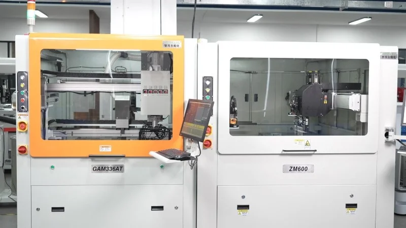
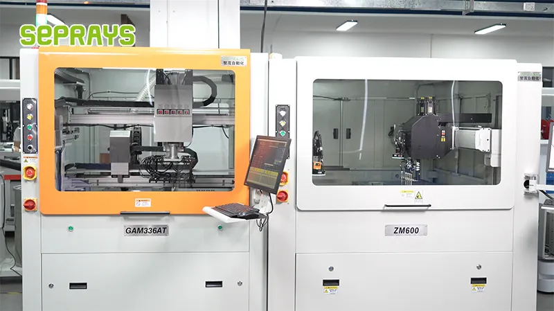
Looking for proven depaneling solutions? Seprays offers a full range of equipment backed by 30+ years of industry experience. Here are two options worth considering for your production line:
- ZM30-D Multi-Tool Multi-Group PCB Depaneling Machine — One-time full LED board cutting — daily output exceeding 100,000 pieces with custom configurations
- GAM330AT Fully Automatic PCB Depaneling Machine — Self-feeding operation with automatic sorting — ideal for high-volume automated production lines
Frequently Asked Questions
Q1: What is the recommended placement position for an inline PCB router within a standard SMT line, and why does placement matter?
A1: The inline router should be positioned immediately after the reflow oven and AOI inspection stage, before any manual handling or board storage. Placing it downstream of AOI ensures that only verified good boards enter the routing process, preventing wasted cycle time on defective assemblies. A buffer system of 2-3 meters between the router and upstream equipment is recommended to accommodate the router’s typical cycle time of 15-30 seconds per board and prevent line bottlenecks.
Q2: How do you handle mixed panel designs on the same SMT line when the router tool path differs between product families?
A2: Modern inline routers support barcode- or camera-based panel identification that automatically loads the corresponding routing program, with typical program switching times under 3 seconds. The tool path library should be pre-validated for each panel variant, including spindle speed (typically 40,000-60,000 RPM) and feed rate parameters, to ensure consistent cut quality across product changeovers. For lines running more than 5 panel variants, a networked recipe management system is recommended to eliminate manual program selection errors.
Q3: What dust and debris management strategies are required when integrating an inline router into a clean SMT production environment?
A3: Inline routers must be equipped with a dedicated dust extraction system rated for at least 4-6 m³/min airflow, paired with HEPA filtration to prevent glass-epoxy particulate contamination of downstream processes. The router enclosure should maintain negative internal pressure relative to the line environment, with sealing strips at board entry and exit ports rated to IP54 minimum. Per IPC-1601 guidelines on PCB handling and storage, any residual dust on routed boards must be removed via an integrated cleaning station—typically a rotating brush module combined with ionized air blow-off—before boards proceed to the next process stage.
About Seprays
About Seprays Precision Machinery
Founded in 1993, Seprays has over 30 years of expertise in PCB depaneling solutions. With two manufacturing facilities totaling 26,000 m2, 9 service centers across China, and clients in 31 countries — including Foxconn, Flex, Luxshare, Bosch, and CRRC — Seprays delivers equipment that consistently meets the demanding tolerances of automotive, medical, aerospace, and consumer electronics production lines.
Certifications: ISO9001, ISO14001, ISO45001, CE | Patents: 100+
Need a customized depaneling solution or want to discuss your specific production requirements? Our technical team is ready to help.
Contact: jimmy@seprays.com


