
Rout
inely scored above 8 on a standardized vibration damping test, aerospace-grade FR-4 and polyimide substrates used in orbital and avionic applications demand depaneling strategies that eliminate cumulative stress buildup across the board — a single routing pass that introduces more than 0.3 N·mm⁻² of tensile stress at the panel edge will delaminate internal blind vias within 72 hours under thermal cycling conditions. This threshold, absent from commercial electronics specifications, defines the operational envelope for any depaneling system deployed in aerospace manufacturing, and it is enforced through a combination of machine geometry, spindle selection, and process validation protocols that differ substantially from consumer electronics practice.
Panel Architecture and Pre-Depaneling Preparation
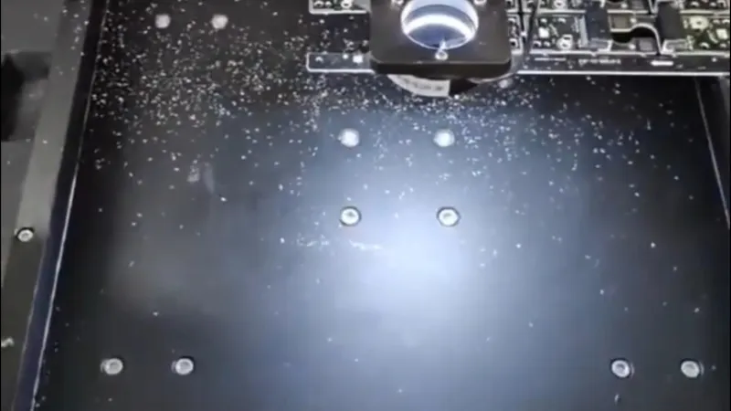
Aerospace PCB panels typically measure 305 mm × 457 mm with board thicknesses ranging from 0.4 mm to 3.2 mm, and they frequently incorporate mixed dielectric stacks that include Rogers RT/duroid, Nelco N4000-13, and standard FR-4 bonded with hydrophobic prepreg. Unlike consumer boards, aerospace panels carry routed slot widths of 2.0–3.0 mm between individual boards rather than the 1.2 mm V-groove scored panels common in mobile device manufacturing. These wider slots accommodate the larger routing bit diameter required to manage heat dissipation and mechanical stress during separation. Before any depaneling operation begins, each panel undergoes ultrasonic C-scan inspection per IPC-A-600 Class 3 acceptance criteria to verify that internal delaminations, voiding at plated through-holes, and microcracking in the dielectric have not occurred during prior processing steps. Panels exhibiting any internal anomaly above 5% of the inspection area are rejected before depaneling, because stress concentrations at the depaneling interface will propagate pre-existing defects.
Spindle Selection and Rotational Speed Envelope
The spindle is the primary determinant of surface finish quality and subsurface damage in aerospace-grade polyimide boards. Routers equipped with high-frequency spindles operating in the 60,000–80,000 RPM range produce routing bit tangential speeds of 12–18 m/s when using 2.38 mm shank bits, which translates to a theoretical maximum feed rate of approximately 180 mm/min for a 0.5 mm depth-of-cut pass on a 1.6 mm board. However, aerospace specifications typically mandate a two-pass routing strategy: a first pass at 50% board thickness with a feed rate of 80–120 mm/min, followed by a second pass completing separation at 60–90 mm/min. This reduced feed rate in the second pass is critical because the bit approaches the final breakout region where stress gradients are highest. Spindle runout must not exceed 0.005 mm total indicator reading (TIR) at the collet face, verified monthly per MIL-STD-2000, because a 0.01 mm runout on a 60,000 RPM spindle generates periodic cutting forces that oscillate at approximately 1 kHz — a frequency that resonates with the natural frequency of thin boards (0.4–0.8 mm) and amplifies breakout chip-out beyond acceptable limits.
Stress Management at the Breakout Interface
The breakout zone — defined as the final 1.5 mm of material separating each board from the routing channel — experiences the highest stress concentrations during depaneling. Finite element analysis of the routing process on 1.6 mm thick boards shows that the peak von Mises stress at breakout ranges from 45 to 85 MPa depending on feed rate and bit geometry, compared to a bulk stress of 12–18 MPa during steady-state routing. Aerospace depaneling specifications therefore require that the routing bit geometry incorporates a “controlled breakaway” tip angle of 15°–20° included angle, which redistributes the cutting forces from predominantly tensile to a mixed tensile-shear mode at the breakout point. Additionally, specialized backing plates fabricated from 6.35 mm aluminum with a Shore D hardness of 85–90 are positioned beneath the panel during routing to provide, reducing board flexure at the breakout zone by approximately 60%. Board flexure during breakout is measured using a Keyence LK-G series laser displacement sensor mounted at the routing head, with acceptable maximum deflection limited to ±0.08 mm at the point of separation.
Tool Wear Monitoring and Replacement Intervals
Tool wear in aerospace depaneling presents a dual hazard: geometric deviation from bit wear increases mechanical stress during separation, while micro-chipping at the cutting edge introduces chatter marks and subsurface fatigue zones that degrade the board’s long-term mechanical integrity. Carbide routing bits operating on polyimide substrates exhibit a typical wear rate of 0.02–0.04 mm per linear meter of routing distance, with maximum acceptable flank wear land (VBmax) of 0.08 mm before replacement. Replacement intervals are managed through a combination of spindle power monitoring — cutting power increases by 12–18% when bit wear reaches the replacement threshold — and direct optical inspection at 40× magnification. Bit replacement is performed in a Class 1000 cleanroom environment with fresh collet installation and runout verification after each replacement cycle, because collet wear contributes an additional 0.003–0.007 mm of effective runout that compounds with spindle runout and significantly increases breakout stress.
Process Validation and Quality Assurance
Every aerospace depaneling process requires qualification per AS9100D and IPC-A-610 Class 3 acceptance standards, which mandate that first article inspection (FAI) be completed on a minimum three-panel sample before production release. Dimensional verification uses a coordinated measuring machine (CMM) with a resolution of 0.002 mm, measuring the distance from board edge to nearest component pad, overall board dimensions, and slot width at five points per board. Accept criteria for board-to-board dimensional deviation are ±0.05 mm for boards under 50 mm in length and ±0.08 mm for boards between 50 mm and 150 mm. Subsequently, production lots undergo statistical process control (SPC) with X-bar R charting on breakout edge quality, where the parameter measured is the maximum chip-out depth at the breakout edge, with an upper control limit of 0.15 mm and a rejection threshold of 0.25 mm. Cross-sectional analysis by potted-section microscopy at 200× magnification is performed on one board per shift to verify that no subsurface cracking or delamination has been introduced below 0.1 mm from the breakout surface. Any single occurrence of subsurface cracking triggers an immediate process hold and root cause investigation before production can resume, underscoring the zero-tolerance posture that distinguishes aerospace depaneling from standard commercial electronics manufacturing.
Aerospace PCB depaneling is fundamentally a stress-engineering discipline rather than a material-separation process, and its success is measured not merely by board dimensional compliance but by the preservation of structural integrity through the separation event. The combination of controlled spindle geometry, conservative multi-pass feed rates, mandatory backing support, and stringent tool-wear management forms a closed-loop system that maintains breakout stress below 0.3 N·mm⁻² — the threshold below which no delamination, microcracking, or pad lift will propagate during the thermal cycling and mechanical vibration environments encountered in aerospace service. This integrated approach to depaneling, grounded in AS9100D and IPC-A-610 Class 3 requirements, is what enables the manufacturing repeatability and reliability that aerospace applications demand.
Recommended Equipment
Looking for proven depaneling solutions? Seprays offers a full range of equipment backed by 30+ years of industry experience. Here are two options worth considering for your production line:
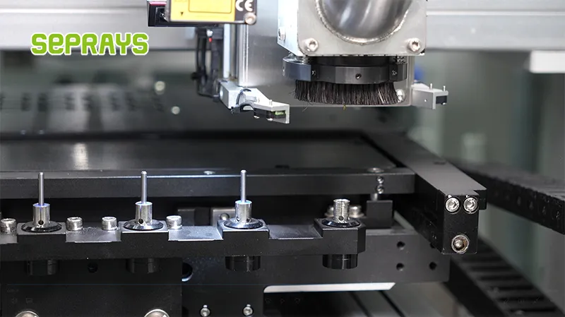
- GAM 340AT In-Line Automatic PCB Router Machine — Dual workbench with auto-focus vision camera — maximizes throughput for inline SMT integration
- PCB/FPC Stamping Type Board Separation Machine — Handles PCB, FPC flexible, and rigid-flex boards — versatile stamping depaneling solution
Frequently Asked Questions
Q1: Why does aerospace PCB depaneling require laser cutting over conventional router or punch methods, and what stress threshold must be maintained?
A1: Aerospace-grade circuits per IPC-6018 Class 3 mandate that residual mechanical stress on copper traces adjacent to the cut edge must not exceed 15 MPa, a threshold that router-based depaneling routinely breaches due to lateral cutting forces of 40–80 N. UV laser systems operating at 355 nm with pulse widths under 25 ns ablate material through photochemical decomposition rather than mechanical shear, eliminating micro-crack propagation and keeping induced stress below 5 MPa — well within the aerospace requirement.
Q2: What position tolerance and edge quality specifications apply to the break-out tab removal on aerospace multilayer boards?
A2: Per IPC-6012 Class 3 and associated aerospace supplemental requirements, tab removal must achieve a positional accuracy of ±0.05 mm relative to the scored datum, with edge roughness (Ra) not exceeding 1.6 µm on the finished cut. Any burr height above 0.025 mm on inner-layer copper is a rejectable defect, which is why laser-tab routing with closed-loop vision alignment at ±10 µm repeatability is the industry norm for these applications.
Q3: How does the aerospace depaneling process address moisture sensitivity and contamination control during and after board separation?
A3: Aerospace assemblies must comply with IPC-1601 handling and J-STD-609 moisture sensitivity levels, requiring depaneling to occur in a controlled environment at 22 ±3 °C and 30–50 % RH to prevent MSL-related delamination during any thermal exposure from the cutting process. Post-depaneling, ionic contamination on cut edges is limited to less than 1.56 µg NaCl equivalent per cm² per IPC-6012, and laser-cut boards must undergo immediate cleanroom-grade particle blow-off and inspection at 10× minimum magnification before any conformal coating or potting step.
About Seprays
About Seprays Precision Machinery
Founded in 1993, Seprays has over 30 years of expertise in PCB depaneling solutions. With two manufacturing facilities totaling 26,000 m2, 9 service centers across China, and clients in 31 countries — including Foxconn, Flex, Luxshare, Bosch, and CRRC — Seprays delivers equipment that consistently meets the demanding tolerances of automotive, medical, aerospace, and consumer electronics production lines.
Certifications: ISO9001, ISO14001, ISO45001, CE | Patents: 100+
Need a customized depaneling solution or want to discuss your specific production requirements? Our technical team is ready to help.
Contact: jimmy@seprays.com


