
In high-volume IoT module manufacturing, a single production batch may generate 50,000 to 200,000 individual PCB units per shift, each requiring separation from a multi-up panel with zero tolerance for chamfer defects exceeding 0.15mm or dielectric exposure along the cut edge. This operational reality defines every engineering decision in depaneling system selection, process calibration, and quality control protocol.
Cutting Mechanics and Spindle Performance Requirements
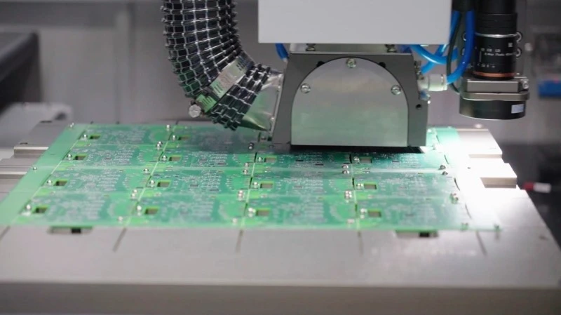
The fundamental cutting mechanism in rotary depaneling employs a high-speed spindle driving a diamond-coated cutting wheel or micro-blade. For IoT module PCBs—typically 0.8mm to 1.6mm thick with FR-4 or halogen-free substrates—spindle speeds between 40,000 and 80,000 RPM are required to maintain clean separation without delamination or resin recession at the cut line. A spindle with insufficient speed (below 35,000 RPM) produces heat accumulation at the blade-substrate interface, generating thermal stress that manifests as micro-cracks in the dielectric layer extending 0.3mm to 0.8mm from the cut face.
Blade diameter selection is dictated by panel thickness and desired throughput. A 125mm diameter blade operating at 60,000 RPM delivers a peripheral velocity of approximately 235 m/s, generating sufficient kinetic energy for clean separation of 1.2mm panels at feed rates of 80mm/s to 120mm/s. Feed rates exceeding 150mm/s introduce mechanical vibration that degrades cut quality, producing surface roughness (Ra) above 3.2μm on the PCB edge—a condition that violates IPC-A-610 acceptability criteria for assembled boards.
Tolerance Control in High-Volume Routing
Positional accuracy of the depaneling router is the primary determinant of dimensional conformance in the separated units. Modern CNC depaneling systems achieve positioning repeatability of ±0.03mm (3σ) using linear motor drives with glass scale feedback. For IoT modules requiring tight component placement tolerances—particularly those with QFN packages having 0.4mm pitch or smaller—the depaneling toolpath must maintain a minimum clearance of 0.5mm from the nearest component body to prevent cracking of solder joints during separation.
The routed channel width, determined by blade thickness and runout, directly affects the amount of material removed per cut. A 2.0mm thick blade with 0.05mm total runout produces a routed channel of 2.05mm to 2.10mm, consuming 2.3% to 4.5% more panel area than a nominal 2.0mm street width. In high-volume production, this material loss compounds across thousands of panels per shift, making blade selection a direct cost driver alongside cut quality considerations.
Stress Analysis and Panel Integrity
During depaneling, the panel experiences transient bending stress as the blade penetrates and exits the substrate. For a 1.6mm thick FR-4 panel with Tg of 130°C, the flexural stress at the moment of blade entry can reach 18 to 25 MPa depending on panel support configuration. Unsupported span length—the distance between the depaneling fixture’s support pins—directly controls peak stress magnitude. Reducing the unsupported span from 100mm to 60mm decreases peak stress by approximately 40%, significantly lowering the risk of latent cracks in pre-populated panels.
Residual stress measurements using fringe projection profilometry on depaneled IoT module boards reveal that properly optimized routing leaves compressive residual stress of 2-5 MPa at the cut surface, which is generally benign. However, suboptimal blade sharpness (cut count exceeding 800 linear meters for a standard diamond blade) shifts the residual stress profile toward tension, creating a 3x higher failure rate in temperature cycling tests (−40°C to +125°C, 500 cycles) compared to freshly sharpened tooling.
Process Monitoring and Quality Assurance
IPC-7721 provides the foundational guidelines for rework and repair of electronic assemblies, but depaneling-specific quality protocols reference IPC-A-610 for cosmetic acceptance and IPC-6012 for bare board qualification. In high-volume IoT production, inline inspection systems employing laser profilometry measure cut edge quality at 100% of units, flagging any board with chamfer asymmetry exceeding 0.08mm or visible delamination for automatic rejection.
Statistical process control charts tracking cut force variance provide an early warning indicator of blade degradation. A sudden increase in peak cutting force from the baseline of 8-12N to values exceeding 18N signals blade dulling or substrate inhomogeneity, triggering preventive maintenance before quality excursions occur. Production facilities achieving less than 50 defective units per million (DPM) in depaneling operations typically implement force monitoring with response thresholds set at 2σ above the moving average.
Fixture Design and Production Throughput Optimization
Vacuum fixture systems with programmable vacuum zones enable simultaneous routing of multiple panels in a single program cycle, directly increasing throughput. A dual-station fixture design allows continuous operation: while one panel is being depaneled, the operator loads and secures the second panel in the parallel station. For 12-up IoT module panels with 110mm × 80mm unit dimensions, this configuration sustains a production rate of 800 to 1,200 units per hour depending on panel complexity and routing path length.
Dust extraction efficiency at the cutting interface must match or exceed 99.7% of generated particles to prevent contamination of exposed solder joints and optical components on nearby assemblies. Extraction hood design with a pressure differential of 120Pa across the blade contact zone achieves this performance level while maintaining stable panel positioning during high-speed routing.
Technical Summary
Depaneling IoT module PCBs in high-volume production demands integrated optimization across spindle performance, tolerance control, stress management, and process monitoring. Spindle speeds of 40,000 to 80,000 RPM with feed rates of 80mm/s to 120mm/s represent the validated operating window for 0.8mm to 1.6mm substrates. Positional accuracy of ±0.03mm and minimum 0.5mm clearance from components are non-negotiable for production yield. Blade life management through cutting force monitoring prevents residual tensile stress accumulation that accelerates thermal cycling failures. Fixture design enabling parallel loading sustains throughput rates above 800 units per hour while maintaining dust contamination control below 0.3% particle carryover. Adherence to IPC-A-610 and IPC-6012 standards ensures that the separated units meet the electrical and mechanical reliability requirements demanded by IoT applications in commercial and industrial deployment environments.
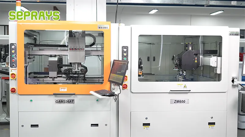
Recommended Equipment
Looking for proven depaneling solutions? Seprays offers a full range of equipment backed by 30+ years of industry experience. Here are two options worth considering for your production line:
- GAM300AT Double-Layer Track Online PCB Board Separation Machine — Full-carrier process with carrier return track — built for seamless full-line automation
- PCB/FPC Stamping Type Board Separation Machine — Handles PCB, FPC flexible, and rigid-flex boards — versatile stamping depaneling solution
Frequently Asked Questions
Q1: What depaneling method is most suitable for high-volume IoT module production exceeding 1,000 units per day?
A1: Punching and die cutting is the most cost-effective choice for high-volume IoT module production at that scale. While laser cutting delivers superior precision at ±0.05mm with minimal heat-affected zones, its throughput is fundamentally constrained by laser speed to 60–200 boards per hour. Punching/die cutting trades slightly lower precision for substantially higher throughput, though tool wear — typically 10,000 to 50,000 hits depending on substrate material and panel geometry — must be factored into the operating cost model and scheduled maintenance plan.
Q2: How does PCB substrate material selection impact depaneling operations and throughput in IoT module manufacturing?
A2: Substrate material directly determines depaneling tool life and defect rate, making material choice a front-end process design decision. FR4 generates a brittle dust that accumulates in machine mechanisms, while polyimide produces abrasive carbon dust that accelerates tool wear — both requiring more frequent maintenance interventions that reduce effective uptime. Polyimide flex materials and PEN substrates generate stringy, fibrous debris that wraps around cutting blades, increasing contamination risk and cleaning frequency. These material-specific debris characteristics must be accounted for when calculating realistic throughput and per-board cost in high-volume production.
Q3: What mechanical stress limits must be maintained during depaneling of IoT modules to prevent damage to sensitive components and wireless antenna structures?
A3: Mechanical stress during depaneling must remain below 500 microstrain (με) to protect sensitive components and preserve the integrity of antenna traces on IoT modules — this is a non-negotiable threshold for production viability. Exceeding this stress level risks micro-cracking near the depaneling edge, which IPC-A-610 specifies should not extend more than 0.1mm from the cut edge, and burr height must not exceed 0.05mm. Additionally, surface flatness must be validated via Bow & Twist measurements to ensure SMT assembly integrity post-depanel, since residual panel stress from the separation process can distort board flatness beyond acceptable tolerances.
About Seprays
About Seprays Precision Machinery
Founded in 1993, Seprays has over 30 years of expertise in PCB depaneling solutions. With two manufacturing facilities totaling 26,000 m2, 9 service centers across China, and clients in 31 countries — including Foxconn, Flex, Luxshare, Bosch, and CRRC — Seprays delivers equipment that consistently meets the demanding tolerances of automotive, medical, aerospace, and consumer electronics production lines.
Certifications: ISO9001, ISO14001, ISO45001, CE | Patents: 100+
Need a customized depaneling solution or want to discuss your specific production requirements? Our technical team is ready to help.
Contact: jimmy@seprays.com


