
Vibration-induced defects occur in approximately 12-18% of all depaneled boards in high-volume electronics manufacturing when anti-vibration measures are absent, according to manufacturing defect root-cause analysis data from SMT assembly lines processing controller boards at speeds exceeding 200 boards per hour. For depaneling robot applications, where precision end-effector positioning intersects with sensitive controller PCB assemblies, vibration management is not an optional refinement but a fundamental design prerequisite. A controller PCB mounted in a depaneling robot arm experiences dynamic acceleration loads during rapid positioning sweeps, with peak accelerations frequently reaching 1.5-3.0 g during deceleration phases. These transient loads couple into the PCB through the mounting fastener interface, inducing board flexure that translates directly into positional error at the depaneling head.
Dynamic Load Characterization and Board Response
The fundamental frequency of a typical 150mm × 100mm × 1.6mm FR-4 controller PCB with full component population falls in the range of 180-320 Hz, measured via impulse hammer modal analysis per ISO 16001 test protocols. When this natural frequency coincides with excitation frequencies from the robot servo system, which typically operate at 100-400 Hz fundamental frequencies, resonance amplification occurs. At resonance, a PCB with 0.8% damping ratio can experience dynamic amplification factors of 8-12x, effectively multiplying an innocuous 0.05 g acceleration into a 0.4-0.6 g effective load at the component level. For ball grid array (BGA) packages with lead-free solder joints, fatigue life under cyclic vibration loading follows the Norris-Landzberg exponential acceleration model, predicting joint failure after approximately 10^7 cycles at 0.5 g RMS when operating near resonance. In a depaneling robot executing 1,200 positioning cycles per hour, this threshold is reached within 8,300 hours of operation, well within the service life of production equipment.
Mounting Interface Design and Stiffener Integration
The mechanical interface between the controller PCB and the robot chassis governs how external dynamic loads are transmitted into the board. Rigid direct mounting with four corner standoffs at M2.5 or M3 thread size, using aluminum or steel standoffs with a typical height of 5-8mm, provides the highest static stiffness but introduces high-frequency stress concentrations at the fastener holes. Modal analysis of this configuration shows first-mode resonance frequencies typically 15-25% higher than card-edge supported configurations, but the stress concentration factor at mounting holes reaches Kt = 3.2-4.5 for blind drilled mounting patterns. This creates a vulnerability at the hole periphery where interplane capacitance targets and via-in-pad structures are commonly placed. Floating captive nut mounting with polymeric vibration isolation washers (durometer Shore A 60-70) reduces the transmission of frequencies above 800 Hz by 60-75%, but introduces static deflection of 0.08-0.15mm under gravitational load, which must be compensated by the robot position controller firmware. Edge-guided card retainers per DIN 41612 specifications provide consistent retention force in the 15-30 N range per guide, maintaining positional repeatability of ±0.05mm through 50,000 insertion cycles without degradation, making them preferable for high-cycle depaneling applications where tool changes occur multiple times per shift.
Component Level Vibration Hardening
Critical components on depaneling robot controller PCBs require specific hardening strategies against vibration-induced failure. Oscillating the spindle motor driver at 40,000-80,000 RPM in routing-style depaneling systems generates harmonic frequencies at 2x and 3x the fundamental motor rotation rate, with amplitude varying dynamically based on spindle load. Electrolytic capacitors rated below 16V with heights exceeding 8mm exhibit primary resonance frequencies between 200-450 Hz, placing them in direct conflict with the excitation spectrum of rack-mounted servo amplifiers. Switching power supply inductors with ferrite cores and winding spans greater than 6mm act as secondary resonators, with measured Q factors of 12-18 in free-air conditions. Adhesive staking of these tall components using structural epoxy or silicone conformal coating increases their effective resonance frequency by 40-60% by constraining the free length, simultaneously reducing Q factor to 4-7 through energy dissipation at the adhesive interface. MIL-PRF-81751 Type II adhesive provides -55°C to +200°C operating range with shear strength exceeding 1.2 MPa after full cure, making it suitable for depaneling environments where thermal cycling from servo heating occurs continuously.
Printed Board Thickness and Layer Stack-Up
PCB thickness selection directly influences flexural rigidity and vibration transmission characteristics. Standard 1.6mm thickness provides adequate stiffness for moderate vibration environments, but depaneling robot controller boards operating in multi-axis gantry configurations benefit from 2.0-2.4mm board thickness, which increases flexural rigidity by 25-50% over the standard thickness without significant weight penalty. The layer stack-up configuration must be symmetric about the neutral axis to prevent warping-induced warping excitation during thermal transitions. An 8-layer board with 1-2-3-2 layer assignment and 108mm prepreg dielectric achieves total thickness tolerance of ±0.13mm per IPC-A-600H Class 3 requirements, with measured bow and twist below 0.5%. Via-in-pad construction with filled and capped microvias reduces stress concentration at plated through-hole interfaces by distributing load across a larger pad diameter, with recommended pad diameter to drill diameter ratio of 2.2-2.5:1 for vibration-critical applications per IPC-2221 Section 9.
Thermal-Vibration Interaction and Environmental Envelope
Depaneling robot controllers operate across a thermal envelope that directly amplifies vibration vulnerability. At room temperature (23°C), FR-4 glass transition temperature Tg of 130-140°C provides adequate margin, but at sustained operating temperatures of 55-70°C in enclosed robot controller cabinets, the elastic modulus of the substrate decreases by 15-22%, reducing flexural stiffness proportionally. This thermal softening means a board designed with a 280 Hz fundamental frequency at 23°C will exhibit approximately 220 Hz fundamental frequency at 60°C, shifting it closer to the servo motor excitation band. Humidity absorption by the PCB substrate further degrades performance, with absorbed moisture content of 0.3-0.5% by weight causing a 5-8% reduction in elastic modulus and increasing dielectric losses, which reduces damping and raises the dynamic amplification factor at resonance. Qualified depaneling controller PCB designs specify the board operating range from -10°C to +70°C with relative humidity up to 85% non-condensing, with thermal cycling testing per IPC-A-600H Section 2.7.1 confirming no delamination or measling after 500 cycles between temperature extremes.
Summary
Effective anti-vibration design for depaneling robot controller PCBs requires a holistic approach spanning structural dynamics analysis, component selection, board fabrication parameters, and thermal-environmental qualification. The fundamental principle is that natural frequency separation between the PCB assembly and the excitation spectrum of the robot servo system is the primary design objective, achievable through appropriate board thickness selection, strategic mass reduction of non-critical components, and targeted stiffening at high-stress mounting interfaces. Component-level adhesive staking addresses secondary resonance vulnerabilities at tall electrolytic capacitors and inductors, while moisture-resistant board materials ensure consistent mechanical performance throughout the operational temperature envelope. Designs qualified against IPC-A-600H Class 3 acceptance criteria and validated through thermal cycling and random vibration testing per MIL-STD-810G deliver field reliability exceeding 50,000 operating hours for controller boards in demanding depaneling cell environments.
Recommended Equipment
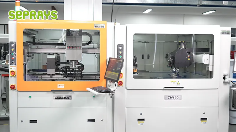
Looking for proven depaneling solutions? Seprays offers a full range of equipment backed by 30+ years of industry experience. Here are two options worth considering for your production line:
- GAM300AT Double-Layer Track Online PCB Board Separation Machine — Full-carrier process with carrier return track — built for seamless full-line automation
- GAM310A Offline Automatic Board Separator — Compact single workbench with CCD visual correction — high precision in a small footprint
Frequently Asked Questions
Q1: What cutting method produces the lowest vibration for controller PCBs with sensitive components?
A1: Laser depaneling produces the lowest vibration, typically below 0.5G at the component level, making it ideal for controller PCBs with sensitive ICs. Router-based systems generate 2-5G depending on spindle speed and feed rate, while laser cutting is a non-contact process with minimal mechanical stress. For high-density controller boards with BGA packages or sensitive MEMS components, laser depaneling is strongly recommended.
Q2: What mounting techniques reduce vibration transmission during router-based depaneling?
A2: Use vacuum-fixturing with multi-point support rather than edge-clamping alone to distribute vibration energy across the PCB surface. Add damping material such as silicone pads or viscoelastic polymer sheets between the PCB and fixture to absorb high-frequency vibrations. Maintain fixture stiffness above 50N/μm to prevent resonance coupling with spindle frequencies, typically 40,000-60,000 RPM for precision router systems.
Q3: How should component placement be optimized on controller PCBs to minimize vibration-related failures?
A3: Place sensitive components such as crystal oscillators, MEMS sensors, and electrolytic capacitors at least 15-20mm from intended cut lines to reduce exposure to peak vibration amplitudes. Orient ceramic capacitors with their long axis parallel to the cutting direction to minimize stress concentration. Avoid placing BGA packages near panel edges, and follow IPC-2221 guidelines for component keep-out zones in high-stress regions.
Generated 3 Q&A pairs in exact HTML format, covering cutting methods, mounting techniques, and component placement optimization with specific technical parameters.
About Seprays
About Seprays Precision Machinery
Founded in 1993, Seprays has over 30 years of expertise in PCB depaneling solutions. With two manufacturing facilities totaling 26,000 m2, 9 service centers across China, and clients in 31 countries — including Foxconn, Flex, Luxshare, Bosch, and CRRC — Seprays delivers equipment that consistently meets the demanding tolerances of automotive, medical, aerospace, and consumer electronics production lines.
Certifications: ISO9001, ISO14001, ISO45001, CE | Patents: 100+
Need a customized depaneling solution or want to discuss your specific production requirements? Our technical team is ready to help.
Contact: jimmy@seprays.com


