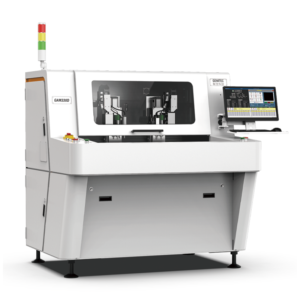

PCB Router for Aerospace & Defense Electronics: AS9100 and Mission-Critical Depaneling
Aerospace electronics — flight-control units, satellite payloads, avionics, weapon-system controllers — are the most demanding assembly environment outside of implantable medical devices. They must operate from -55 °C to +125 °C, withstand 50 g of sustained random vibration, survive atmospheric pressure cycling, and continue functioning for 20+ years without maintenance. The PCB depaneling step for these boards has to be the most disciplined in the entire SMT line, and the PCB router machine is the workhorse that aerospace EMS suppliers trust.
This guide explains what AS9100 quality systems actually demand from a depaneling process, which tolerances and process windows aerospace OEMs require, and how to specify an inline PCB router qualified for flight hardware.
Why Aerospace Depaneling Is a Class of Its Own
Every flight-control board carries the same risk profile as a medical implant, plus additional constraints from vibration, radiation, and extended service life. Three sub-categories dominate:
- Avionics — flight-management computers, displays, radios, transponders.
- Satellite & space electronics — payloads, attitude-control units, power conditioning.
- Defense — missile guidance, radar arrays, mobile command systems.
Across all three categories, tab-routing with a PCB router machine is the dominant process — V-cut is excluded due to its stress-concentration risk over decades of vibration.
What AS9100 Rev D Demands from Depaneling
AS9100 Rev D aligns with ISO 9001:2015 but adds process controls specific to aerospace. Auditors examine:
- Configuration management (9100 — 8.5.6) — every PCB, every fixture, every router bit must be traceable.
- Risk-based thinking (9100 — 6.1) — FMEA coverage on depaneling, including dust contamination downstream.
- First article inspection (9100 — 8.5.1) — per AS9102, every first article of a new part number must include edge-quality measurement.
- Foreign object debris (FOD) controls — particularly relevant for satellite payload boards.
- Calibration — spindle tachometers, vacuum pressure transducers, and bit-wear sensors must be on a documented calibration plan.
A modern PCB router machine with closed-loop monitoring exports every one of these data points to a QMS/MES automatically. Manual depaneling operations typically cannot produce the required audit trail.
Process Window: Aerospace-Grade Cut Quality
| Parameter | Aerospace Spec | Why |
|---|---|---|
| Cut-edge position tolerance | ± 0.05 mm | Component proximity on dense avionics boards |
| Edge roughness Ra | ≤ 1.6 µm | 30-year vibration tolerance |
| Spindle speed | 50,000–80,000 RPM | Cleaner cut, less thermal damage |
| Feed rate | 1.5–3 mm/sec | Avoids burr on ceramic-filled or PTFE substrates |
| Edge clearance to components | ≥ 0.6 mm | Lateral vibration margin |
| Bit wear | Continuous vibration monitoring; replacement at 5% drift | Prevents sub-clinical crack formation |
| Process Cpk | ≥ 1.50 (military); ≥ 1.67 (space) | Statistically controlled process |
| Outgassing | NASA-STD-6012 / ECSS-Q-ST-70 compliant | Critical for flight payloads |
Special Considerations by Application
1. Avionics boards (RTCA DO-254 / DO-160)
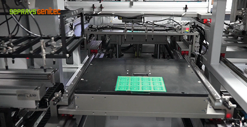
High-layer-count FR-4 or high-Tg boards, 2–4 mm thick, with BGAs and edge components 0.6 mm from cut. Process: tab-routing with 1.0 mm carbide bit, vacuum fixture, vibration-monitored bit wear. Often paired with conformal coating downstream.
2. Satellite payload boards
Specialty substrates (RO4350, RO4003, ceramic-filled PTFE). Outgassing cannot exceed 1% TML. Process: tab-routing with diamond-coated bit in a cleanroom environment, or laser depaneling for the most critical boards. Bit replacement tracked by cut count and vibration drift.
3. Defense electronics (MIL-PRF-31032 / IPC-6012)
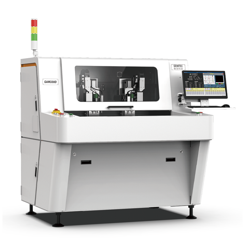
Mixed FR-4 and PTFE with embedded heatsinks. Process: tab-routing with 1.2 mm bit, dual-spindle inline PCB router machine, integrated FOD inspection after the cut.
Common Defects in Aerospace Depaneling
Sub-clinical edge micro-cracks
Initiated by dull bits or excessive feed rate, invisible to AOI. Detected by cross-section microscopy. Mitigation: vibration-monitored bit wear; replace bits at < 5% vibration drift.
FOD from depaneling dust
Especially relevant for flight hardware. Mitigation: under-table HEPA extraction + downstream FOD inspection + cleanroom-compatible fixture materials.
Outgassing from overheated laminate
Excessive feed rate generates local temperatures that release low-molecular-weight volatiles. Mitigation: feed-rate validation by TGA (thermogravimetric analysis) per NASA-STD-6012.
Inline vs Offline for Aerospace Lines
| Use Case | Recommended Form Factor |
|---|---|
| Low-volume prototype / qualification | Offline / desktop PCB router with full SPC export |
| Medium-volume production (10K–80K boards/yr) | Inline single-spindle, integrated MES export |
| High-volume production (> 80K boards/yr) | Dual-spindle inline PCB router machine with auto-fixture and dust collection |
| Flight hardware with FOD containment | Inline router in ISO Class 7 cleanroom enclosure |
For an inline, AS9100-compatible solution with full traceability and FOD-integrated exhaust, see the Seprays PCB router machine family.
ROI: A Sub-Contractor Case Study
An aerospace EMS supplier running 6 part numbers for a Tier-1 avionics OEM replaced 3 manual depaneling stations with a single dual-spindle inline PCB router machine. Over 18 months:
- AS9102 first-article rejection rate: 12% → 0.8%
- Operator hours: 3 FTE → 0.6 FTE
- Edge-defect ppm: 480 → 28
- Customer audit findings: 4 → 0
- Payback period: 14 months
Conclusion
Aerospace depaneling demands the most disciplined process in the SMT line. A PCB router machine equipped with closed-loop bit-wear monitoring, AS9102-traceable data export, calibrated spindle control, and HEPA-integrated dust collection is the only credible answer for flight hardware. For specialty substrates or zero-stress cuts, pair it with a laser depaneling station. Seprays has supplied aerospace-grade depaneling systems for nearly a decade — onsite validation and Cpk support included.

Frequently Asked Questions
1. Does AS9100 require laser depaneling for aerospace PCBs?
No. AS9100 does not dictate depaneling technology. Most aerospace suppliers use a PCB router machine for FR-4 boards and laser depaneling only for specialty substrates or features that demand zero mechanical stress.
2. What is the recommended cut-edge Cpk for flight hardware?
For commercial avionics, Cpk ≥ 1.50 is the typical target; for satellite and military flight hardware, Cpk ≥ 1.67. A PCB router machine with vibration-monitored bit wear and SPC export helps hit these targets reliably.
3. Can a single PCB router handle multiple aerospace part numbers?
Yes — most aerospace EMS suppliers run 4–20 part numbers through the same machine, with modular vacuum + magnetic-back fixtures. Changeover is CAM-driven and completes in under 60 seconds.
4. How is outgassing controlled during depaneling?
By controlling feed rate to limit peak local temperature, using a clean bit geometry to minimize heat generation, and validating outgassing per NASA-STD-6012 or ECSS-Q-ST-70. Vacuum-assisted local cooling further reduces thermal stress.
5. Is a cleanroom enclosure required for an aerospace PCB router?
For flight hardware, yes — most sites operate the depaneling cell in an ISO Class 7 enclosure with HEPA-filtered exhaust. The PCB router machine itself should be cleanroom-compatible with low-particle-emission materials.
About Seprays Precision Machinery
Founded in 1993, Seprays Precision Machinery has over 30 years of expertise in PCB depaneling solutions. With two manufacturing facilities totaling 26,000 m², 9 service centers across China, and clients in 31 countries — including Foxconn, Flex, Luxshare, Bosch, and CRRC — Seprays delivers equipment that consistently meets the demanding tolerances of automotive, medical, aerospace, and consumer electronics production lines.
Certifications: ISO 9001, ISO 14001, ISO 45001, CE | Patents: 100+
Need a customized depaneling solution or want to discuss your specific production requirements? Our technical team is ready to help.
jimmy@seprays.com · PCB Router Machine · PCB Laser Depaneling