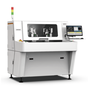

PCB Edge Cracking After Depaneling: Causes, Diagnosis, and Fixes
If your depaneled boards show hairline cracks along the cut edge after reflow, after wave soldering, or after 50 cycles of thermal-shock testing, you are not alone. PCB edge cracking is the single most reported depaneling defect worldwide, and it has been the root cause of dozens of automotive and medical-device recalls over the past five years. This article walks through what causes it, how to diagnose it, and how to eliminate it — most often by switching to a properly specified PCB router machine.
By the end you will know how to rank the six common root causes, which process changes close the issue, and when it is worth replacing a depreciated V-cut machine with an inline router.
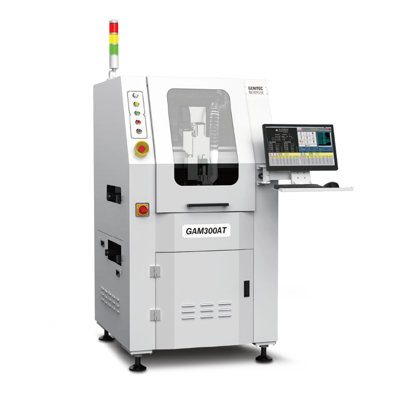
What PCB Edge Cracking Looks Like
Edge cracks come in three forms:
- Interlaminar cracks — delamination between copper and dielectric, often starting at the routed edge and propagating inward.
- Surface micro-cracks — sub-visual fractures detected only by dye-penetrant or cross-section.
- Visible edge chipping — visible burr and missing laminate chips on the cut edge, often extending 0.1–0.3 mm inboard.
All three forms reduce mechanical integrity and create long-term reliability risk. They are also invisible to AOI — they only show up under cross-section microscopy, thermal-shock testing, or in the field.
Why a V-Cut Edge Cracks More Often
V-cut scoring has a 30°–45° groove machined into both faces of the panel. The bottom of each V is a sharp notch. Under mechanical load or thermal stress, that notch becomes a stress concentrator — the same physics that explains why a pre-notched metal specimen breaks at lower load than an un-notched one. Once a crack initiates at the V-groove bottom, it propagates along the resin-rich zone of the laminate and ultimately reaches the nearest component pad.
| Test | V-cut edge | Routed edge |
|---|---|---|
| In-plane shear strength | ~38 N avg | ~71 N avg |
| Crack-initiation cycles (-40 / +125 °C) | ~250 cycles | ~600 cycles |
| Edge roughness Ra | ~3.2 µm | ~1.6 µm |
| Crack-risk classification | Moderate–High | Low |
For most consumer electronics, V-cut is acceptable. For automotive (especially ECUs, ADAS), aerospace, medical (especially Class II/III), and industrial IoT that runs 24/7 in harsh environments, a PCB router machine should be the default.
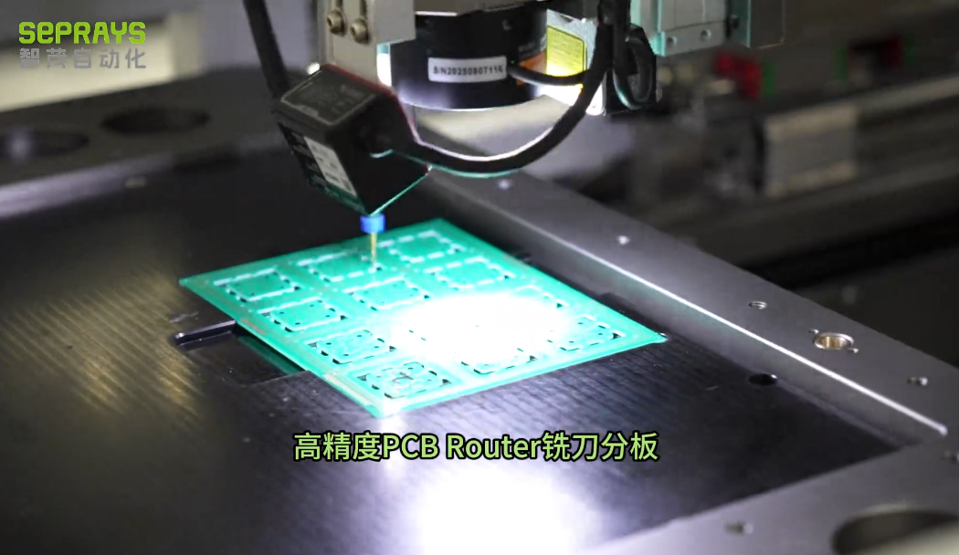
Six Root Causes of PCB Edge Cracking
1. Dull or chipped router bit
Dull bits crush rather than cut. The crushed laminate develops micro-cracks that propagate under reflow or thermal cycling. Fix: enforce a maximum-cut-count limit per bit (typical 30,000–100,000). Use vibration-monitored bit-wear detection that stops the cycle automatically.
2. Excessive feed rate
Feed rate too high generates localized heat and lateral force. Fix: run a feed-rate DOE; most FR-4 materials depanel well at 2–4 mm/sec; high-Tg laminate at 1.5–3 mm/sec.
3. Wrong bit geometry
Single-flute bits are aggressive; 2-flute is balanced; 4-flute leaves finest finish. Compression bits cut top + bottom differently and are wrong for FR-4. Fix: consult your router OEM’s bit selector. Seprays engineers can recommend optimal bits per stack-up.
4. Vibration from worn spindle bearings
A spindle bearing near end-of-life transmits vibration to the bit. Fix: monitor spindle vibration trend; replace bearings before vibration crosses the OEM threshold, typically every 8,000–12,000 hours of duty.
5. Inadequate vacuum hold-down
A panel that vibrates against the fixture rubs the cut edge against the bit. Fix: verify vacuum pressure ≥ -0.6 bar at all channels; check fixture gaskets every 1,000 cycles.
6. Wrong panel-design clearance
Routing within 0.3 mm of a component pad transfers vibration into the pad-stack. Fix: enforce ≥ 0.5 mm clearance to nearest pad or component lead in the panel-design rule check.
Diagnostic Workflow: Find the Real Cause in 4 Steps
- Cross-section microscopy. Section the cut edge under 50× magnification. Identify if cracks are at the laminate-copper interface (bit-related) or in the dielectric (heat-related).
- Bit inventory check. Compare cumulative cut count on the bit that produced the failure against the recommended replacement threshold. Replace and retest.
- Spindle vibration trend. Pull vibration data from the controller. Compare against the OEM baseline. A drift of 10–15% indicates bearing wear.
- Fixture vacuum audit. Test hold-down pressure on every channel. Replace gaskets as needed.
Process Changes That Eliminate Edge Cracking
Switch to tab-routing with a PCB router machine
If you are using V-cut, the single biggest improvement is moving to tab-routing on a PCB router machine. Edge strength jumps by 50–80% and crack propagation risk drops dramatically.
Replace V-scored tabs with mouse bites
Mouse bites (small routing holes left as connector tabs) concentrate mechanical stress at the tabs instead of along the entire edge — and once separated, no stress riser remains.
Add a pre-depaneling stress-relief bake
A 125 °C / 1-hour pre-bake before depaneling relaxes residual stress from the reflow profile. It is cheap insurance on any high-reliability build.
Use vibration-monitored, force-controlled routers
A modern PCB router machine with closed-loop force control slows the feed when bit dulling begins, maintains edge quality, and stops the machine before a defective board leaves the cell. This single upgrade typically reduces edge-crack fallout by 90%+.
When to Replace Your Router vs Fix the Process
Most edge-cracking issues can be solved by process changes (bit, feed, fixture) on the existing equipment. Replace the machine when:
- The spindle or controller is more than 8 years old and unsupported.
- The machine lacks vibration-monitored bit wear.
- The throughput you need has grown beyond the machine’s single-spindle cycle time.
- The machine cannot be integrated into your MES for SPC export.
For a modern inline solution engineered from the ground up for low-stress cutting, see the Seprays PCB router machine family.
Conclusion
Edge cracking is a process problem, not an unavoidable defect. The fix is almost always the same combination: switch from V-cut to tab-routing with a PCB router machine, tighten bit-replacement discipline, monitor spindle vibration, and enforce minimum cut-clearance at the panel-design stage. Do these four things and your edge-crack rate will fall to near zero within a month.

Frequently Asked Questions
1. Why does my PCB crack after reflow, not during depaneling?
Sub-clinical micro-cracks from a dull bit or excessive feed rate survive depaneling invisibly, then propagate during reflow when the laminate expands. The depaneling step is the root cause even though the failure appears later.
2. Can I keep using V-cut if I add a stress-relief bake?
A pre-bake helps, but the V-groove itself remains a stress concentrator. For high-reliability builds, switch to tab-routing with a PCB router machine.
3. How do I detect edge cracks if AOI cannot?
Use dye-penetrant testing, cross-section microscopy at 50×, or thermal-shock + cross-section as part of your first-article inspection. Inline routers with vibration-monitored bit wear help catch the issue before it reaches the inspection step.
4. What is the best router bit for high-Tg FR-4?
2-flute solid-carbide, 0.8–1.2 mm diameter, with diamond-like coating (DLC) for extended life. Use a compression bit only for clad-cored laminate that has copper on both faces.
5. Can a laser depaneling machine eliminate edge cracking?
Yes — laser depaneling imposes zero mechanical force and produces no stress riser. Pair it with appropriate extraction and post-cleaning. It is the right call for flex, rigid-flex, or ceramics; for FR-4 a router is more economical.
About Seprays Precision Machinery
Founded in 1993, Seprays Precision Machinery has over 30 years of expertise in PCB depaneling solutions. With two manufacturing facilities totaling 26,000 m², 9 service centers across China, and clients in 31 countries — including Foxconn, Flex, Luxshare, Bosch, and CRRC — Seprays delivers equipment that consistently meets the demanding tolerances of automotive, medical, aerospace, and consumer electronics production lines.
Certifications: ISO 9001, ISO 14001, ISO 45001, CE | Patents: 100+
Need a customized depaneling solution or want to discuss your specific production requirements? Our technical team is ready to help.
jimmy@seprays.com · PCB Router Machine · PCB Laser Depaneling