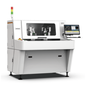

5G base stations, millimeter-wave antennas, and telecom switches have depaneling requirements that ordinary FR-4 lines do not. The laminate materials are exotic — PTFE composites, RO4000 series, modified epoxy with ceramic filler — the tolerances are tight, and the cut-edge quality directly affects RF performance. A PCB router machine chosen for a 5G production line has to be different from one chosen for a consumer phone line.
This guide explains what 5G-specific depaneling demands, how to specify the right PCB router, and how to integrate it with the SPC and traceability systems that Tier-1 telecom OEMs require.
Why 5G PCBs Depanel Differently
Three differences dominate:
- Material. RO4350B, RO4003C, RT/duroid 5880, modified PTFE composites. These are abrasive, soft, and tend to smear under inappropriate bit geometry.
- Tolerance. Impedance-controlled traces need ± 25 µm positioning tolerance. A 0.1 mm cut deviation matters.
- Edge effect. Antenna traces run close to the panel edge. Cut quality affects return loss and insertion loss.
The result: 5G depaneling rejects ordinary FR-4 routing parameters. Spindle speed, feed rate, bit geometry, and vacuum hold-down all need to be validated on the actual stack-up.
Process Specification for High-Frequency Laminate Depaneling
| Parameter | 5G Spec | Why |
|---|---|---|
| Spindle speed | 50,000–80,000 RPM | Cleaner PTFE cut, less smearing |
| Feed rate | 1.5–3 mm/sec | Avoids heat-induced dielectric changes |
| Bit material | Solid carbide, diamond-like coating (DLC) | Abrasive laminate wears conventional bits |
| Bit life | Replace at ≤ 5,000 cuts (RO4350B); ≤ 30,000 (RO4003C) | Abrasive wear breaks tolerance |
| Cut-edge clearance | ≥ 0.7 mm (RF traces) | Preserves impedance-controlled geometry |
| Edge roughness Ra | ≤ 1.6 µm | Minimizes passive intermodulation (PIM) distortion |
| Vacuum hold-down | ≥ 0.7 bar | PTFE composites flex; without hold-down, the panel bows during cut |
| Dust extraction | Dedicated extraction per spindle + HEPA H13 | PTFE dust is bioactive and toxic |
Selecting the PCB Router for 5G
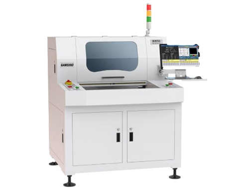
A PCB router machine for 5G production should have:
- High-speed spindle (≥ 60,000 RPM) — needed for the PTFE-family materials.
- Vibration-monitored bit wear — critical for abrasive laminates where bit life varies.
- Diamond-coated or DLC bits as standard fixture (not aftermarket).
- High-resolution CCD vision — sub-pixel alignment for ± 25 µm positioning.
- Cleanroom-compatible exhaust — PTFE / ceramic dust must not enter the production area.
- CAM-side integration — direct import of impedance-controlled CAD files.
For a high-frequency capable solution, see the Seprays PCB router machine family with optional PTFE tooling package.
Common 5G Defects and Their Root Causes
Edge smearing on PTFE composites
PTFE smears at low spindle speeds, leaving behind a glossy edge. Fix: 60K+ RPM, 2-flute DLC bit, sharp contact angle.
PIM (passive intermodulation) degradation
Rough cut edges generate harmonics in RF circuits. Fix: edge roughness ≤ 1.6 µm; validate with a PIM analyzer on first-article samples.
Impedance drift near the cut edge
Lateral force distorts microstrip / stripline geometry within 0.3 mm of the cut. Fix: 0.7 mm edge clearance + force-controlled feed.
Bit wear on long production runs
PTFE is more abrasive than FR-4 by 5–10×. Fix: vibration-monitored bit wear + auto-stop at 5,000 cuts.
Three 5G Application Sub-Categories
1. Macro base station antennas (64T64R / 128T128R)
Large multilayer boards, often 6–8 layers of RO4350B. Edge tolerance ± 0.05 mm. Process: dual-spindle inline PCB router machine with vibration-monitored bit wear; throughput target ≥ 15 sec/board.
2. Millimeter-wave modules (24/28/39 GHz)
Miniaturized boards with PTFE laminate and cavity structures. Process: single-spindle router with 60K+ RPM; often paired with laser depaneling for the cavity edges.
3. Small cells / FWA (fixed wireless access)
Mid-size boards with mixed FR-4 / RO4350. Process: inline single-spindle router with auto-fixture; throughput 12–18 sec/board.
Compliance and Quality
Tier-1 telecom OEMs (Ericsson, Nokia, Huawei, ZTE, Samsung) require:
- Telcordia GR-78 / GR-326 — telecom-grade reliability documentation.
- TL 9000 — quality management for telecom supply chain.
- RF test reports on depaneled boards covering PIM, return loss, and insertion loss.
- Full traceability — every panel linked to its router bit, spindle, operator, and dust-extractor cycle.
A modern PCB router machine with MES export generates all of these reports automatically; manual depaneling cannot produce them.
ROI: A 5G OEM Case Study
A European 5G base-station OEM running 18,000 boards/month on 12 part numbers replaced their manual depaneling operation with an inline PCB router machine:
- PIM-related defect rate: 1.8% → 0.2%
- Operator hours: 2.5 FTE → 0.5 FTE
- Bit consumption: down 35% (DLC bits + vibration monitoring)
- Payback: 10 months
- Customer audit findings on depaneling: 5 → 0
Material-Specific Quick Reference
| Material | Spindle Speed | Feed | Bit Coating |
|---|---|---|---|
| RO4350B | 60–80K RPM | 2–3 mm/sec | DLC preferred |
| RO4003C | 60–80K RPM | 2–3 mm/sec | DLC preferred |
| RT/duroid 5880 | 50–70K RPM | 1.5–2.5 mm/sec | DLC required |
| Modified PTFE composite | 60–80K RPM | 2–3 mm/sec | DLC required |
| Hybrid FR-4 + RO4350 stack-up | 50–60K RPM | 2 mm/sec | Carbide, no DLC |
Conclusion
5G and telecom PCBs are a distinct class of depaneling. The PCB router machine for these applications needs a 60K+ RPM spindle, diamond-coated or DLC bits, vibration-monitored bit wear, and HEPA-integrated dust extraction. With those specifications, an inline router delivers 10–14 month payback for mid-volume 5G OEMs. For more aggressive specs, pair the router with a laser depaneling station for PTFE cavity cuts. Seprays supplies both, with PFTE-laminate tooling and 5G-specific fixtures.

Frequently Asked Questions
1. Can a standard PCB router handle RO4350B?
Technically yes, but with high bit wear (carbide bits last 500–1,500 cuts on RO4350B). For production volumes, a router with DLC bits and vibration-monitored wear extends bit life to 5,000+ cuts and keeps tolerances tight.
2. Why does PTFE-dust require special handling?
PTFE dust is biologically active and toxic when heated. HEPA H13 filtration and dedicated exhaust are required; never let PTFE dust enter the general factory ventilation.
3. What’s the Cpk target for 5G cut edge quality?
For 5G antenna boards, Cpk ≥ 1.50 is the typical target; for millimeter-wave modules with ± 25 µm tolerance, Cpk ≥ 1.67. A PCB router machine with vibration-monitored bit wear helps you reach these targets.
4. Should I use laser depaneling for 5G boards?
Often — for cavity cuts, tight-tolerance features, and PTFE/ceramic stacks. Many Tier-1 5G suppliers run a hybrid cell: a PCB router machine for the main outline, and a laser depaneling station for precision features.
5. How long do DLC bits last on RO4350B?
5,000–8,000 cuts is the typical envelope, depending on stack-up and feed rate. Vibration-monitored routers replace bits before tolerance drifts outside spec, regardless of cut count.
About Seprays Precision Machinery
Certifications: ISO 9001, ISO 14001, ISO 45001, CE | Patents: 100+
Need a customized depaneling solution or want to discuss your specific production requirements? Our technical team is ready to help.
jimmy@seprays.com · PCB Router Machine · PCB Laser Depaneling