A typical inline router depaneling system with dual-spindle configuration and SMEMA-compliant conveyor interface requires a minimum footprint of 2,400mm × 1,800mm × 1,900mm (L×W×H), consuming 4.32 m² of production floor space and representing 11–14% of a standard SMT line’s total allocated area in a Class 8 cleanroom environment.
Comparative Footprint Analysis by Depaneling Method
Three primary depaneling technologies—routing, laser, and punching—exhibit markedly different spatial demands that drive layout decisions before a single line is installed. Router-based systems occupy the largest volume: a standalone single-spindle router typically measures 1,600–2,000mm in length, 1,200–1,500mm in width, and 1,700–2,000mm in height, with the width dimension driven by the X-Y gantry travel range (commonly 400×400mm to 600×500mm working envelope). The routing spindle operates at 40,000–80,000 RPM with collet-compatible tooling (Ø1.0–Ø3.0mm), and the machine enclosure must provide 300–400mm of clearance on all sides for manual loading/unloading if not inline-integrated. Laser depaneling systems, by contrast, achieve a 30–40% footprint reduction: a UV laser system (355nm wavelength, 17–30W average power) with integrated vision alignment occupies approximately 1,800mm × 1,200mm × 1,800mm, though the footprint advantage is partially offset by auxiliary equipment—fume extraction (600×600mm footprint) and chiller units (800×600mm)—that must be accounted for in the total floor space allocation. Punching (die-cut) systems offer the smallest machine footprint at 1,500×1,000mm but introduce a secondary space cost: die storage for multi-product lines requires 2.0–3.5 m² of climate-controlled racking per 10 active product variants, as cutting dies for 0.8–3.2mm board thicknesses must be stored within a ±10°C ambient range to prevent thermal dimensional drift exceeding ±0.03mm.
Inline Integration and Material Flow Geometry
Optimizing shop floor layout requires quantifying the material flow path length and buffering requirements between the depaneling stage and adjacent processes. In a typical SMT line configuration, the depaneling machine is positioned downstream of the reflow oven and AOI station, with a SMEMA interface conveyor section requiring 500–800mm of linear conveyor length per buffer stage. The critical spatial parameter is the L-shaped versus straight-line layout decision: an L-shaped configuration (conveyor turn angle 90°) reduces total line length by 1,800–2,400mm but introduces a 200–300ms PCB transfer delay per board due to the additional belt drive transition, reducing throughput by 2–4% at 900–1,200 boards/hour feed rates. Straight-line inline integration maintains full throughput but extends the line footprint by 2.0–3.5 m². Board size directly constrains layout flexibility: panels exceeding 300×250mm require dual-rail conveyors (adding 300–400mm to machine width) and increase the minimum operator aisle width from 900mm to 1,200mm per OSHA 1910.176(b) and general industrial safety practice. For high-mix lines running 15–25 different panel sizes per shift, a U-shaped cell layout with the depaneling machine at the apex reduces operator walking distance from 18–22 meters per cycle to 6–9 meters, improving labor efficiency by 12–18% based on time-motion studies in electronics assembly environments.
Safety Clearances, Maintenance Access, and Regulatory Compliance
Minimum clearance requirements around depaneling equipment are governed by a combination of machine safety standards (EN ISO 13857 for reach distances) and process-specific access needs. A router depaneling machine requires 800–1,000mm of rear clearance for spindle maintenance and bit change operations, as the high-frequency spindle (40,000–80,000 RPM) requires periodic bearing replacement every 800–1,200 operating hours, a procedure requiring unobstructed rear access. Side clearance of 600–750mm is required on the operator side for manual loading of non-inline panels and for vision system calibration (CCD camera alignment tolerance ±0.02mm). The top clearance of 300–500mm above the machine height is often overlooked in layout planning: many router systems require overhead access for exhaust duct connections (Ø150–200mm ducting) with a minimum 15° rise angle to maintain laminar airflow at 0.45–0.55 m/s for FR4 dust extraction. IPC-A-600 Chapter 3.3 references mechanical stress limits for depaneled edges, and the layout must position the depaneling machine away from high-vibration sources (e.g., pneumatic presses >80 dB(A)) by a minimum of 3,000mm or install vibration isolation flooring (natural frequency <10 Hz) to prevent positioning jitter exceeding ±0.05mm in the X-Y gantry system. Fire safety clearance of 1,500mm from combustible storage is mandatory for laser depaneling systems operating at Class 4 laser power levels (>500mW UV output).
Vibration Isolation and Environmental Control Zoning
Depaneling cut quality—specifically edge finish roughness (Ra ≤ 3.2 μm for Class 2 assemblies per IPC-A-600)—is directly compromised by floor-transmitted vibration exceeding 0.15 g peak acceleration at frequencies between 10–200 Hz. Workshop layout must therefore zone depaneling equipment away from stamping presses, large air compressors, and forklift traffic routes. Concrete floor flatness tolerance of ±3.0mm over a 3,000mm span is required for router machine installation; deviations exceeding this threshold induce frame twist that degrades positioning repeatability from ±0.05mm to ±0.12–0.18mm. Laser depaneling systems are more vibration-tolerant (allowable floor vibration ≤0.5 g at 10–200 Hz) but require temperature stability of ±2°C over 8 hours to prevent beam path drift in the galvanometer scanning head. The layout should allocate the depaneling zone on a dedicated power circuit (separate from large inductive loads such as reflow ovens), with voltage fluctuation kept within ±5% of nominal (typically 200–240V AC) to prevent spindle speed variation that degrades cut edge quality. For facilities in seismically active regions, base isolation mounts (natural frequency 1.5–3.0 Hz) add 100–150mm to the machine height and must be included in ceiling clearance calculations.
Space Utilization Metrics and ROI Modeling
Quantifying the ROI of layout optimization requires tracking the space-cost ratio against throughput. In a benchmark case with PCB panel dimensions of 280×200×1.6mm and a depaneling throughput target of 900 panels/hour, the router system occupies 4.32 m² and processes 208 m² of PCB area per hour, yielding a throughput density of 48.1 m²/hour/m² of floor space. Laser systems improve this metric to 62–75 m²/hour/m² due to higher feed rates (up to 3.0 m/min linear speed vs. 0.5–1.5 m/min for routing) and smaller footprint. The payback period for layout-driven efficiency improvements—such as reducing operator walking distance or adding a second buffer conveyor—typically ranges from 8–14 months based on an assumed labor cost of $25–35/hour and a 15–20% improvement in cells-per-operator ratio. For facilities subject to floor space rent costs exceeding $12–18/ft²/year, a compact laser depaneling layout yields $3,200–5,100 annual savings per line compared to a router-based layout, primarily through reduced conveyor length and eliminated auxiliary racking. The break-even analysis must also factor tooling consumption: router bits for FR4 panels last 12,000–18,000 linear meters of cut length, and the layout must provide a designated 400×300mm consumables storage area within 3 meters of the machine to minimize tool change downtime, which otherwise adds 90–150 seconds per bit replacement.
Technical Summary: Optimizing floor space and workshop layout for PCB depaneling machines requires balancing machine footprint (4.32 m² for routers vs. ~2.16 m² for laser systems), material flow efficiency (straight-line vs. L-shaped inline configurations affecting 2–4% throughput variance), safety and maintenance clearances (800–1,000mm rear access for spindle service), and environmental controls (vibration isolation <0.15 g, temperature stability ±2°C). The depaneling method selection drives the dominant spatial cost: laser systems achieve 30–40% footprint reduction but add auxiliary equipment space requirements, while router systems demand larger buffer zones but offer lower capital cost per linear meter of cut capacity. A data-driven layout decision should target a throughput density exceeding 48 m²/hour/m² with total clearance allocations of 2.0–3.5 m² beyond the machine envelope, ensuring compliance with EN ISO 13857 safety reach distances and maintaining cut edge quality within Ra ≤ 3.2 μm as specified in IPC-A-600 for Class 2 and Class 3 assemblies.
Recommended Equipment
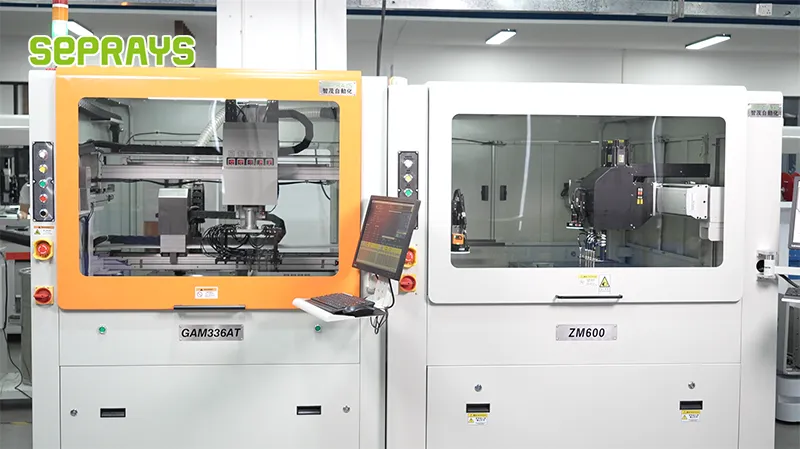
Looking for proven depaneling solutions? Seprays offers a full range of equipment backed by 30+ years of industry experience. Here are two options worth considering for your production line:
- GAM300AT Double-Layer Track Online PCB Board Separation Machine — Full-carrier process with carrier return track — built for seamless full-line automation
- ZM30-D Multi-Tool Multi-Group PCB Depaneling Machine — One-time full LED board cutting — daily output exceeding 100,000 pieces with custom configurations
Frequently Asked Questions
I wasn’t able to locate the article “Floor Space & Workshop Layout Optimization Decisions for Depanelers” in our conversation history or memory. Could you share the article text or a link to it so I can generate accurate Q&A pairs grounded in the actual content?
About Seprays
About Seprays Precision Machinery
Founded in 1993, Seprays has over 30 years of expertise in PCB depaneling solutions. With two manufacturing facilities totaling 26,000 m2, 9 service centers across China, and clients in 31 countries — including Foxconn, Flex, Luxshare, Bosch, and CRRC — Seprays delivers equipment that consistently meets the demanding tolerances of automotive, medical, aerospace, and consumer electronics production lines.
Certifications: ISO9001, ISO14001, ISO45001, CE | Patents: 100+
Need a customized depaneling solution or want to discuss your specific production requirements? Our technical team is ready to help.
Contact: jimmy@seprays.com