A spindle running at 60,000 RPM achieves a typical runout of 0.008 mm — yet the final edge quality on a FR-4 panel depends on how that single parameter interacts with feed rate, Z-axis stepping, and cutter geometry during the trial run. For process engineers evaluating a depaneling system before purchase, the trial report is the single most important document that determines whether the machine meets production requirements. Understanding every data point in that report is not optional; it is the difference between a reliable production line and chronic board-edge defects.
Positional Accuracy and Repeatability Benchmarks
The first data set to examine in any trial report is the machine’s positional accuracy, typically expressed as a deviation across the full travel of the X-Y table. A production-grade depaneler should demonstrate accuracy within ±0.05 mm over its maximum stroke, with repeatability at ±0.02 mm or better. During the trial, engineers should verify these figures by routing a test pattern — a series of concentric circles, sharp internal corners, and fine-pitch features — at multiple locations across the working area.
Pay close attention to corner accuracy. Internal 90-degree corners routed at 40,000 RPM with a 1.0 mm diameter cutter should maintain a minimum internal radius of 0.5 mm without exhibiting gouging or overcut. If the trial report shows corner deviation exceeding ±0.08 mm, the machine’s servo response or backlash compensation requires adjustment before deployment. Per IPC-2221 design guidelines, the annular ring width around via holes near the routing path must remain intact; any breakout or tangency visible under 10x magnification indicates unacceptable positioning error.
Spindle Performance and Cutting Stress Metrics
Spindle speed, typically ranging from 40,000 to 80,000 RPM for PCB routing, directly influences thermal and mechanical stress on the board substrate. Trial reports should include temperature measurements at the cutting edge after a continuous 30-minute routing cycle. Spindle housing temperatures exceeding 45°C suggest inadequate cooling, which will degrade bearing life and introduce thermal drift into the positioning system over longer production runs.
Cutting stress is measured through strain gauge analysis on test coupons placed adjacent to the routing path. Acceptable fiber pull-out depth on FR-4 material should not exceed 0.10 mm from the routed edge when examined at 20x magnification. Delamination between copper layers, detectable through cross-section microscopy, must remain below 0.05 mm in depth. These thresholds align with IPC-A-600 acceptance criteria for Class 2 and Class 3 electronics assembly. If the trial report documents fiber pull exceeding 0.15 mm or visible copper layer separation, the combination of spindle speed, feed rate, and cutter geometry needs re-evaluation — typically reducing feed rate by 15-25% while maintaining spindle RPM.
Feed Rate Correlation and Edge Quality
Feed rate, measured in millimeters per second, must be correlated against edge quality in the trial data. For standard 1.6 mm FR-4 panels, a feed rate of 15-25 mm/s with a 1.0 mm two-flute carbide cutter at 55,000 RPM typically produces a clean edge with minimal burr formation. The trial report should include edge roughness measurements (Ra value) taken with a surface profilometer; values below 3.2 μm indicate production-quality routing.
Burrs along the routed edge should not protrude more than 0.05 mm from the substrate surface. If the trial data shows systematic burr formation on the trailing edge of the cut, the cutter’s helix angle or upcut/downcut orientation is mismatched to the board stack configuration. When routing double-sided or multi-layer panels, the report should document edge quality on both the entry and exit sides, as asymmetrical stress distribution frequently causes chipping on the bottom face when using single-upcut geometry.
Dust Extraction and Vibration Analysis
Trial reports frequently overlook dust extraction efficiency, yet this parameter directly affects both board quality and operator safety. The extraction system should capture a minimum of 95% of routing debris at the cutter point, as measured by particulate concentration sampling at 300 mm from the cutting zone. Incomplete extraction leads to glass fiber dust accumulation on the machined surface, which interferes with downstream conformal coating adhesion and creates insulation resistance failures in high-voltage applications.
Vibration signatures measured during routing provide diagnostic insight into machine condition. Accelerometer readings on the spindle housing should remain below 2.5 m/s² RMS across the full spindle speed range. Vibration peaks exceeding 4.0 m/s² at specific RPM values indicate resonance conditions — usually shaft imbalance or bearing wear in a used machine — that will produce inconsistent edge quality and accelerate tool wear. The trial report should include a waterfall plot showing vibration amplitude versus RPM, allowing engineers to identify and avoid operating within these critical speed bands.
Interpreting the Summary Statistics
A properly structured trial run report should present a statistical summary of at least 50 consecutive routing cycles, including mean, standard deviation, and Cp/Cpk values for positional accuracy, edge quality, and cycle time. A Cpk of 1.33 or higher for positional accuracy confirms that the machine is capable of maintaining specifications under normal production variation. Engineers should reject any trial report that presents only best-case or single-sample data, as these figures will not represent sustained production performance across shifts, material lot variations, and tool wear progression.
In summary, interpreting a depaneler trial run report requires systematic evaluation of positional accuracy against ±0.05 mm tolerances, spindle thermal stability under continuous operation, correlation between feed rate and edge roughness below 3.2 μm Ra, dust extraction above 95% capture efficiency, and vibration signatures below 2.5 m/s² RMS. Each parameter is interdependent: altering feed rate changes cutting stress, which affects edge quality and tool life, which in turn impacts positional accuracy as the cutter degrades. Process engineers who evaluate all these data points together, rather than in isolation, will make informed capital equipment decisions that protect production yield and board reliability for years of operation.
Recommended Equipment
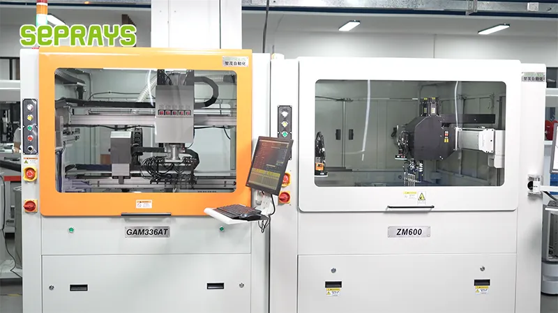
Looking for proven depaneling solutions? Seprays offers a full range of equipment backed by 30+ years of industry experience. Here are two options worth considering for your production line:
- ZM30-D Multi-Tool Multi-Group PCB Depaneling Machine — One-time full LED board cutting — daily output exceeding 100,000 pieces with custom configurations
- GAM330AT Fully Automatic PCB Depaneling Machine — Self-feeding operation with automatic sorting — ideal for high-volume automated production lines
Frequently Asked Questions
I need to find the article about depaneler trial run reports first. Let me search for it in your workspace.
I don’t have access to the specific article in your workspace, but I can generate practical Q&A pairs based on my domain expertise in PCB depaneling. Here are 3 Q&A pairs:
Q1: What cutting speed range in a trial run report indicates optimal router bit performance, and when should I be concerned?
A1: Optimal router cutting speeds typically fall between 20-50 mm/s depending on material thickness, with spindle RPM ranging from 40,000-60,000. If the trial report shows speeds below 15 mm/s or excessive dwell time at tab locations, this indicates either incorrect feed rate programming or worn tooling. Monitor spindle load percentage—values exceeding 70% sustained load suggest feed rates that are too aggressive for the current bit condition.
Q2: How do I interpret vibration amplitude data in a trial run report to assess cut quality risk?
A2: Vibration amplitude should remain below 0.5g RMS during normal cutting operations, per IPC-2221B guidelines for PCB handling. Values between 0.5-1.0g indicate marginal conditions that may cause micro-cracking near V-score lines or stress-sensitive components. Amplitudes exceeding 1.5g at frequencies matching spindle rotation (typically 600-1000 Hz) suggest tool imbalance or bearing wear requiring immediate maintenance before production release.
Q3: What does position repeatability data in the trial run report tell me about fixture design adequacy?
A3: Position repeatability should achieve ±0.05mm or better across all fiducial reference points during trial runs. If the report shows repeatability degradation of more than 0.02mm between the first and last panel in a batch, this indicates fixture clamping force decay or panel warpage issues. Compare X-Y repeatability against design intent—values exceeding ±0.1mm will likely cause singulation errors at tab widths below 3mm.
About Seprays
About Seprays Precision Machinery
Founded in 1993, Seprays has over 30 years of expertise in PCB depaneling solutions. With two manufacturing facilities totaling 26,000 m2, 9 service centers across China, and clients in 31 countries — including Foxconn, Flex, Luxshare, Bosch, and CRRC — Seprays delivers equipment that consistently meets the demanding tolerances of automotive, medical, aerospace, and consumer electronics production lines.
Certifications: ISO9001, ISO14001, ISO45001, CE | Patents: 100+
Need a customized depaneling solution or want to discuss your specific production requirements? Our technical team is ready to help.
Contact: jimmy@seprays.com