PCB depaneling machines executing router-based separation at 60,000 RPM generate cutting forces between 0.8-2.4 N depending on feed rate and bit wear state, yet the control software’s ability to visualize and compensate for these forces varies dramatically across equipment platforms—with some systems providing real-time cutting stress overlays and others offering only basic G-code playback with no force feedback integration.
Operator Interface Architecture and Menu Hierarchy Depth
Depaneling machine control software diverges sharply in menu structure complexity. Systems built on modular GUI frameworks present program setup within 2-3 screen levels, with cutting parameter adjustment (feed rate: 3-15 mm/s; spindle speed: 30,000-80,000 RPM) accessible directly from the main program screen. In contrast, older-generation software architectures require navigation through 6-8 nested menu levels to reach critical process variables such as Z-axis cutting depth (typically 0.3-0.8 mm below PCB bottom surface), tool retraction height, and bit-condition monitoring thresholds. Touchscreen responsiveness varies from 8 ms to 45 ms measured at the HMI layer, directly affecting operator efficiency during manual teach-point entry. Software platforms compliant with IPC-2221B design guidance integrate DFM rule-checking at the program verification stage, flagging insufficient web widths (<0.5 mm between routed slots and SMT components) before program execution.
CAD File Import Pipeline and Geometry Parsing Accuracy
GERBER (RS-274-X) and ODB++ file import represents a critical usability differentiator. High-performance control software parses Gerber apertures and flash definitions directly, auto-recognizing board outline layers (GKO, GKO-LAYER, or *.outline) and generating separation toolpaths with <±0.03 mm deviation from imported geometry. Mid-tier systems require manual layer mapping and often introduce scaling drift of ±0.1-0.15 mm when converting DXF spline entities to linear segment approximations. ODB++ import preserves netlist topology and component placement data, enabling software-level stress analysis that identifies high-risk separation zones near BGAs and fine-pitch QFP packages. Feed rate auto-allocation based on local copper density—higher copper areas requiring 15-25% feed reduction to manage cutting torque—is present only in software platforms with integrated CAM engines rather than basic G-code interpreters.
Real-Time Process Monitoring and Adaptive Control Integration
Control software with inline force feedback from spindle load monitoring (sampling at 1-2 kHz) adjusts feed rate dynamically within a ±30% envelope to maintain cutting stress below 40-50 MPa at the board edge—a threshold established by IPC-9691B HALT testing as the approximate limit before solder joint micro-cracking initiates. Systems lacking adaptive control operate at fixed feed rates, risking edge stress spikes of 70-90 MPa when encountering localized FR-4 glass transition zones or epoxy filler variations. Software that superimposes real-time cutting force heat maps onto the board layout graphic enables operators to identify chronic high-stress regions and modify toolpath geometry accordingly. Bit wear compensation algorithms—automatically reducing Z-depth by 0.005-0.01 mm per 500 mm of cut length—maintain edge quality consistency across production runs exceeding 5,000-8,000 boards per tool.
Error Diagnostics, Alarm Granularity, and Maintenance Accessibility
Diagnostic interface quality varies from basic alarm code displays (“Error 37: Spindle Fault”) to structured fault trees with 40-60 diagnostic nodes tracing failures to specific hardware subsystems (spindle inverter, X/Y/Z servo drive, vacuum pressure transducer). Software with integrated current signature analysis detects impending spindle bearing failure at 72-120 hours before catastrophic seizure, displaying remaining service life as a percentage on the maintenance dashboard. Alarm acknowledgment workflows differ substantially: some platforms require physical pushbutton confirmation at the machine HMI, while others permit remote alarm clear via networked software clients. Spindle run-time logging with cumulative bearing load history enables condition-based maintenance scheduling aligned with IPC-6012 Section 3.6 structural integrity requirements. Multi-language software localization (Simplified Chinese, English, German, Japanese, Korean) uses UTF-8 encoding with all error strings externalized in editable resource files, allowing custom translation without firmware recompilation.
Recipe Management, Parametric Programming, and Production Changeover
Program storage architectures range from flat-file systems limited to 200-500 programs to database-driven repositories supporting 10,000+ programs with metadata tagging (PCB part number, panel size, thickness range 0.4-3.2 mm, tooling type). Quick-changeover workflows—switching from a 1.6 mm thick FR-4 panel program to a 0.8 mm polyimide rigid-flex program—take 45-90 seconds with software that supports parametric program scaling and automatic tool offset recalculation. Version control with SHA-256 checksum validation prevents unauthorized program modification and provides audit trails for ISO 9001 and IATF 16949 compliance documentation. Batch production interfaces displaying real-time yield (boards processed vs. boards with edge-quality alarms) with SPC chart integration (X-bar and R-chart) enable operators to detect tool wear trends before they exceed ±0.05 mm edge-position tolerance limits.
Technical Summary
Control software usability in PCB depaneling machines centers on three measurable performance axes: programming time per new PCB type (ranging from 8 minutes on software with automated toolpath generation to 35-50 minutes on manual teach-pendant systems), diagnostic resolution (alarm granularity spanning 15-20 fault categories versus 60-80 with subsystem-level tracing), and process adaptability (fixed-parameter execution versus real-time force-feedback loop with <50 ms correction latency). Systems integrating ODB++ import with DFM rule verification reduce field edge-quality failures by an estimated 40-60% compared to Gerber-only import workflows, while adaptive feed control limits cutting stress to <50 MPa versus 70-95 MPa with fixed-parameter execution. Software architectures supporting parametric programming and checksum-validated recipe management reduce changeover time to <90 seconds and provide the documentation integrity required for aerospace and automotive supply chain audits.
Recommended Equipment
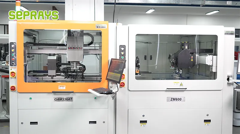
Looking for proven depaneling solutions? Seprays offers a full range of equipment backed by 30+ years of industry experience. Here are two options worth considering for your production line:
- ZM30-D Multi-Tool Multi-Group PCB Depaneling Machine — One-time full LED board cutting — daily output exceeding 100,000 pieces with custom configurations
- GAM330AT Fully Automatic PCB Depaneling Machine — Self-feeding operation with automatic sorting — ideal for high-volume automated production lines
Frequently Asked Questions
Q1: How does operator training time compare between modern touchscreen-based control software and traditional button-pendant interfaces for PCB depaneling machines?
A1: Touchscreen-based systems with graphical previews typically require 4-6 hours of training for basic operation, whereas button-pendant systems often need 2-3 days due to nested menu structures and lack of visual feedback. The reduction in training time directly translates to faster line changeover and reduced dependency on specialized operators.
Q2: What programming time can I expect when setting up a new PCB panel profile in different control software platforms?
A2: Modern PC-based control software with CAD import capabilities can reduce programming time to 15-30 minutes per new panel profile, compared to 2-4 hours for systems requiring manual coordinate entry. Automatic tool path generation and built-in stress simulation further reduce setup time while preventing costly cutting errors.
Q3: How do different control software platforms handle error diagnostics and recovery during production runs?
A3: Advanced control software provides real-time stress monitoring with automatic spindle speed adjustment when cutting forces exceed 0.5N, while basic systems only trigger emergency stops without diagnostic detail. Software with built-in error logging and remote diagnostics capability reduces mean time to repair (MTTR) from 45-60 minutes to under 15 minutes.
About Seprays
About Seprays Precision Machinery
Founded in 1993, Seprays has over 30 years of expertise in PCB depaneling solutions. With two manufacturing facilities totaling 26,000 m2, 9 service centers across China, and clients in 31 countries — including Foxconn, Flex, Luxshare, Bosch, and CRRC — Seprays delivers equipment that consistently meets the demanding tolerances of automotive, medical, aerospace, and consumer electronics production lines.
Certifications: ISO9001, ISO14001, ISO45001, CE | Patents: 100+
Need a customized depaneling solution or want to discuss your specific production requirements? Our technical team is ready to help.
Contact: jimmy@seprays.com