
The following sections explain how both dust collection methods work, what factors affect their performance, and how to evaluate the right configuration for your PCB routing application.
1. How Top and Bottom Dust Collection Work on PCB Router Machines
Top dust collection and bottom dust collection actually have the same goal:
Remove chips and dust from the cutting area as soon as they are generated.
What changes is where the suction airflow is created and how the suction structure is arranged around the router bit and PCB.
This follows the general principle of local exhaust ventilation. OSHA explains that dust-control systems are more effective when contaminants are captured close to their source. Although this guidance is not specific to PCB routing, the same source-capture principle is useful when evaluating dust collection around a routing process.
OSHA guidance on local exhaust ventilation and dust control
1.1 What Is Top Dust Collection?
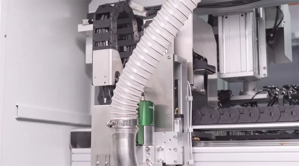
Top dust collection places the main suction hood or suction inlet above the PCB, normally around the spindle and router-bit working area.
As the router bit cuts the board, dust can be captured by the airflow near the upper cutting area and transported through the duct to an external dust collector.
Typical airflow path: Cutting area → Top suction hood → Dust duct → Dust collector
The actual collection performance depends on factors such as suction-hood position, available component clearance, duct design, airflow, and the distance between the suction inlet and the cutting point.
1.2 What Is Bottom Dust Collection?
Bottom dust collection creates the main suction area below the PCB.
Dust and cutting debris can pass through routing openings, fixture slots, or dedicated bottom airflow channels before entering the dust collection system.
Typical airflow path: Cutting area → Fixture slot / bottom airflow channel → Suction system → Dust collector
Because the main collection path is arranged below the board, this structure can provide more freedom above the PCBA in some applications. However, whether it is suitable still depends on the actual component layout, fixture design, and machine structure.
2. Top Dust Collection vs Bottom Dust Collection: Key Differences
2.1 Performance, Structure, and Application Comparison
| Comparison | Top Dust Collection | Bottom Dust Collection |
|---|---|---|
| Main suction position | Above the PCB | Below the PCB |
| Typical dust path | Toward an upper suction hood | Through fixture openings or bottom channels |
| Top-side space | Requires space for the suction structure | May leave more open space above the PCBA |
| Fixture design focus | Suction-hood position and component clearance | Routing slots, sealing, and bottom airflow path |
| PCBAs with taller components | Top-side clearance should be checked | May offer more layout flexibility in some cases |
| Main collection consideration | How effectively the upper suction inlet covers the cutting area | How effectively the fixture directs airflow toward the cutting area |
Neither structure is automatically more effective. Dust collection performance depends on how well the suction path is designed around the actual cutting area.
2.2 How Dust Collection Relates to Upcut and Downcut Routing
The spindle position can influence how conveniently a dust collection system is arranged, but it does not create a fixed requirement for top or bottom suction.
With an upcut PCB router structure, the spindle is located above the PCB, so a top suction hood may be convenient to integrate around the spindle area.
With a downcut PCB router structure, the main cutting mechanism is positioned below the PCB, so bottom airflow channels may be easier to incorporate into the machine or fixture design.
However, these are structural tendencies rather than mandatory combinations.
Upcut or downcut routing does not automatically determine whether top or bottom dust collection must be used. The final configuration should be evaluated from the complete machine, fixture, PCB, and dust-control design.
2.3 How Router-bit Spiral Direction Affects Chip Removal
The spiral geometry of a router bit can influence how chips move during cutting, but top or bottom dust collection does not require a fixed left-hand or right-hand spiral.
There is no universal rule that top dust collection must use one spiral direction or bottom dust collection must use another.
The router bit should instead be selected according to the PCB material, board thickness, routing path, cutting quality requirements, tool specification, and overall process design.
Chip movement is only one factor in the dust collection system. Suction position, airflow, fixture openings, tool geometry, and cutting parameters can all affect how efficiently debris leaves the routing area.
NIOSH has documented the use of local exhaust ventilation close to cutting tools as an engineering control for dust generated during machining operations. Although these applications differ from PCB routing, the same general principle of capturing dust near its source is relevant.
3. Which Applications Are Better Suited to Top or Bottom Dust Collection?
The most useful selection factors are component clearance, machine structure, fixture design, and the actual dust collection path.
3.1 When Can Top Dust Collection Be a Good Choice?
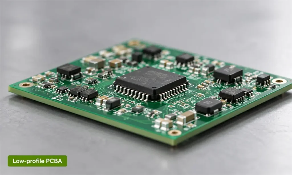
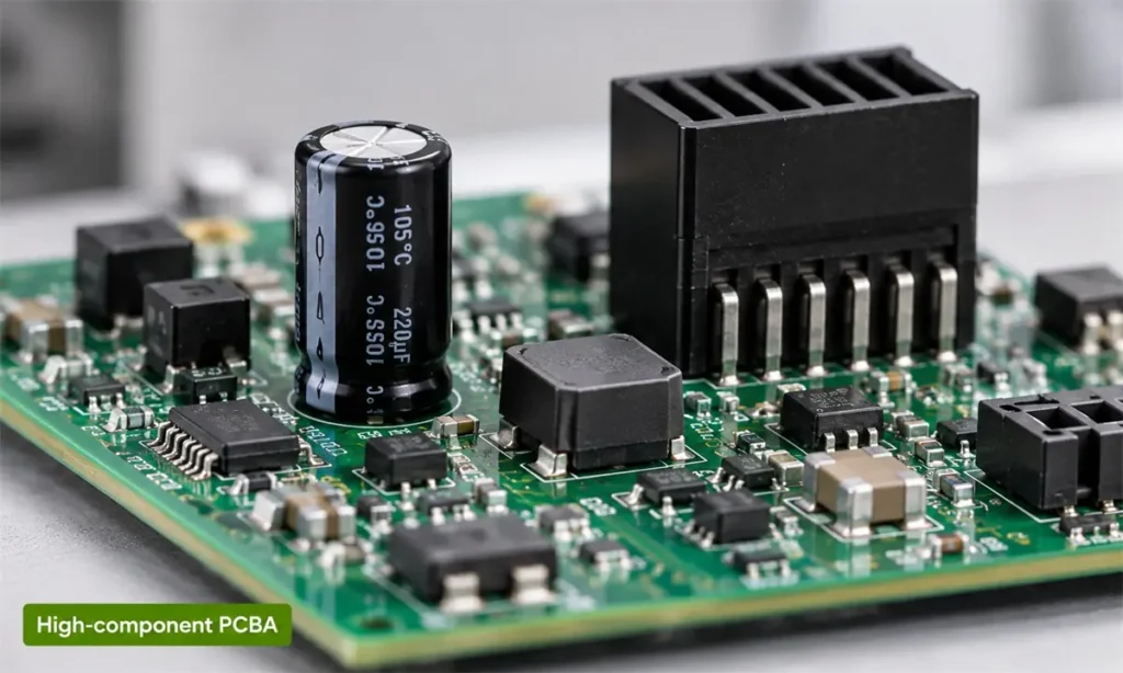
Top dust collection can be practical when there is enough space above the PCB for the suction hood to operate close to the cutting area without interfering with components.
Typical situations may include:
- standard FR4 PCB routing;
- PCBAs with relatively low-profile top-side components;
- routing paths with sufficient clearance around nearby components;
- machine structures where an upper suction hood can be conveniently integrated;
- fixtures where building a complete bottom airflow channel is less practical.
The main point is not whether the PCBA has components on the top side, but whether the suction structure has enough safe operating clearance.
If the hood must be positioned farther from the cutting area to avoid components, the actual collection result should be verified under real production conditions.
3.2 When Can Bottom Dust Collection Be a Good Choice?
Bottom dust collection can be practical when the fixture and machine structure allow dust to be drawn through openings beneath the cutting area.
Typical situations may include:
- PCBAs where top-side space is relatively limited;
- products where placing a suction hood above the routing area is less convenient;
- machine structures that can accommodate bottom suction channels;
- fixtures designed with routing openings or dedicated airflow paths;
- applications where the bottom structure allows suction to remain close to the cutting area.
For bottom dust collection, fixture design can have a significant influence on performance.
The objective is to guide enough airflow through the actual cutting area, rather than simply creating the largest possible opening beneath the PCB.
Oversized openings or excessive air leakage may spread the available suction over a wider area, so fixture design should be evaluated together with the dust collection system.
4. How to Choose Between Top and Bottom Dust Collection
Instead of starting with a fixed rule, evaluate the actual routing application step by step.
4.1 Quick Selection Checklist
1. Where is the spindle and cutting mechanism located?
The machine structure affects where a suction system can be installed most conveniently, but it does not automatically determine the final dust collection method.
2. How much clearance is available around the PCBA?
Check component height and position on both sides of the board. The goal is to make sure the spindle, tool, suction structure, and fixture can operate without interference.
3. What router bit and cutting process will be used?
Router-bit geometry can influence chip movement, but there is no fixed requirement that a certain spiral direction must be paired with top or bottom dust collection.
4. Can the suction path stay close to the routing area?
Whether suction comes from above or below, it should be designed to capture debris near the actual cutting position.
5. Can the fixture support both stable routing and effective airflow?
Fixture support, routing openings, sealing, and component clearance should all be considered together.
Machine structure → PCBA clearance → Tool and cutting process → Suction path → Fixture design
If the correct configuration is difficult to determine from drawings alone, sample cutting can provide a clearer reference.
SEPRAYS can evaluate PCB or PCBA samples, component layout, routing paths, fixture requirements, and machine configuration to help determine a suitable dust collection solution and verify it through actual cutting tests.
5. Frequently Asked Questions
5.1 Does PCB material affect the choice of dust collection system?
PCB material can affect the amount and type of debris generated during routing, but it does not by itself determine whether top or bottom dust collection should be used.
Material should be considered together with board thickness, routing length, tool selection, cutting parameters, and the available dust collection structure.
5.2 Does a thicker PCB require stronger dust collection?
Not necessarily.
A thicker PCB may generate more cutting debris because more material is removed along the routing path, but the required dust collection performance also depends on routing length, cutting speed, tool size, airflow path, and production volume.
The better approach is to evaluate whether the system can maintain stable chip removal during continuous routing rather than relying on board thickness alone.
5.3 Can dust collection affect routing quality?
Dust collection does not directly define the routing accuracy of the machine.
However, keeping excessive debris away from the cutting area can help maintain a cleaner fixture and routing environment, which is beneficial for stable continuous production.
5.4 Does top dust collection require a specific router-bit spiral direction?
No fixed left-hand or right-hand spiral is required simply because the machine uses top dust collection.
Router-bit selection should be based on the PCB material, cutting path, desired edge quality, tool specification, and actual process test results.
5.5 Does bottom dust collection require a specific router-bit spiral direction?
No.
Bottom dust collection also does not automatically require a particular spiral direction. The tool and dust collection system should be evaluated as separate but related parts of the overall routing process.
5.6 How can I tell whether the current dust collection system is working well?
A practical way is to inspect the routing area after continuous production, especially:
- the PCB surface;
- the fixture and routing slots;
- the area around the cutting tool;
- the inside of the machine near the routing station.
If excessive debris repeatedly remains in these areas, the suction position, ducting, fixture airflow, cutting process, or dust collector setup may need to be reviewed.
5.7 Should dust collection be tested with the actual PCBA before buying a machine?
For complex products, sample testing is useful because actual component height, board structure, fixture design, and routing path can affect the final dust collection result.
A real cutting test can show whether the selected configuration provides enough clearance and keeps the routing area acceptably clean under realistic operating conditions.
5.8 What information should I provide when evaluating a dust collection solution?
Useful information includes:
- PCB or PCBA samples;
- panel dimensions and board thickness;
- component height and layout on both sides;
- routing path or Gerber / DXF files;
- PCB material;
- planned production volume;
- fixture or machine requirements, if already known.
With this information, the PCB, tool, fixture, machine structure, and dust collection method can be evaluated as one complete routing process.
Conclusion
Top and bottom dust collection are both practical solutions for PCB routing, and neither one requires a fixed router-bit spiral direction or a fixed upcut/downcut pairing.
The more reliable approach is to evaluate the machine structure, PCBA clearance, cutting process, fixture, suction path, and actual routing result together.
For projects with complex PCB structures or uncertain dust collection requirements, SEPRAYS can support sample cutting and process evaluation to help determine a suitable configuration before the final machine setup is confirmed.