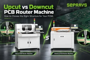

The main difference between an upcut and downcut PCB router machine is the position of the spindle and cutting tool, which directly affects component clearance during depaneling.
1. How Upcut and Downcut PCB Router Machines Work
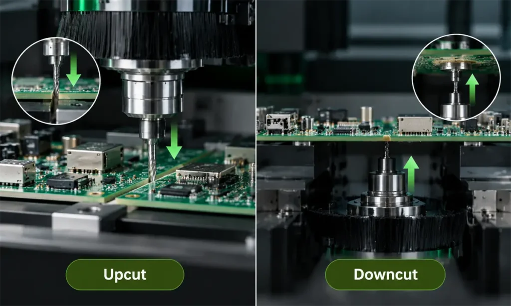
An upcut PCB router machine places the spindle above the PCBA, so the router bit enters the board from the top side.
A downcut PCB router machine places the spindle below the PCBA, allowing the router bit to cut from underneath.
The cutting direction itself does not determine which machine is more accurate. The main difference is how much clearance is available around the components during routing.
With an upcut design, the spindle, tool holder and router bit all need enough space above the board. A downcut design frees more space on the top side, which is why it is often used for PCBAs with taller components.
2. Which Applications Are Better Suited to Upcut and Downcut Routers?
| Application Condition | Upcut | Downcut |
|---|---|---|
| Standard PCBA | Suitable | Suitable |
| Low-profile top-side components | Suitable | Suitable |
| Tall components on the top side | Requires careful clearance evaluation | Usually more suitable |
| Tall components close to the routing path | Higher interference risk | Easier to avoid top-side interference |
| Complex bottom-side components | Often easier to arrange | Bottom clearance must be checked carefully |
Both structures are mature depaneling solutions. The key is not to decide which one is “better,” but which one provides safer component clearance and a more suitable fixture layout for the actual PCBA.
3. How Should You Choose the Right PCB Router Machine?
A practical way to choose is to check the PCBA in the following order.
Step 1: Check where the tallest components are located.
Step 2: Check how close those components are to the routing path.
Step 3: Check whether the bottom side also has components that could interfere with the fixture or cutting tool.
If tall components are concentrated on the top side and sit close to the routing path, a downcut structure usually provides more clearance.
If the top-side components are low enough and the spindle can move safely above the panel, an upcut structure can also be a good choice.
The selection should therefore be based on:
Top-side component height + bottom-side component height + routing path + fixture clearance
When these four conditions are clear, the upcut/downcut decision becomes much more straightforward.
4. PCB Material, Board Thickness and Panel Structure Selection Reference
After determining the cutting direction, the next step is to evaluate the PCB itself.
For common FR4, multilayer PCB and irregular panel designs, the following factors are especially important:
- PCB thickness;
- panel dimensions;
- board rigidity;
- tab or connection-point position;
- distance between components and the routing edge;
- whether the panel is easy to warp;
- router-bit diameter and available routing gap.
Thin boards and large panels usually require stronger fixture support because deformation during routing can affect cutting consistency.
Example: Downcut clearance reference
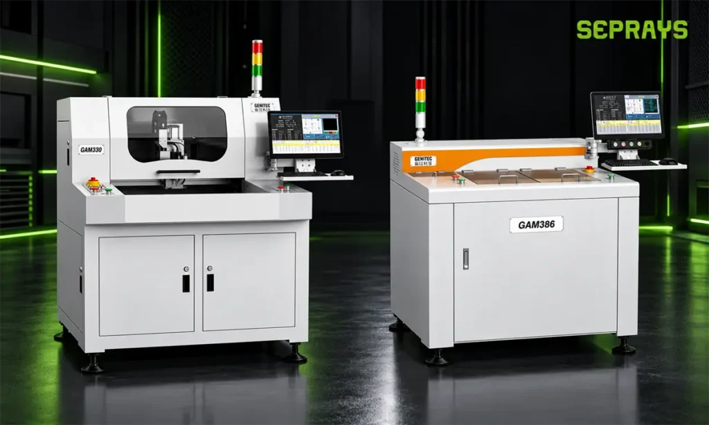
For the SEPRAYS GAM386 downcut router, the PCBA structure can be evaluated with the following clearance references:
- Top-side component height: ≤ 50 mm
- Bottom-side component height: ≤ 15 mm
- PCBA cutting diameter: within 55 mm
These values help determine whether the actual PCBA fits within the physical cutting space of the machine.
Material, board thickness, panel structure and fixture support still need to be evaluated together. The cutting direction alone should never be the only selection criterion.
5. What Should Be Checked During Sample Cutting?
For PCBAs with tall components or complicated layouts, sample cutting is often the most reliable way to confirm whether an upcut or downcut structure is more suitable.
During the test, check the following:
-
- whether the spindle or router bit interferes with any component;
- whether both top and bottom sides have enough clearance;
- whether the routed edge is clean and consistent;
- whether the PCB warps or vibrates during cutting;
- whether the fixture supports the panel correctly;
- whether the actual cycle time meets the production target.
Real assembled PCBAs are especially useful for this evaluation because actual component height, soldering tolerance and fixture thickness may differ from the drawing.
SEPRAYS provides PCB/PCBA sample cutting and process evaluation services.
Customers can provide physical samples, Gerber or DXF files, PCB thickness, panel dimensions, top- and bottom-side component heights, and production targets. The engineering team can then evaluate tool clearance, routing direction, fixture design and suitable process conditions before machine selection.
6. Upcut vs Downcut PCB Router Machine: Selection Summary
Upcut and downcut PCB router machines are both effective depaneling solutions; the right choice mainly depends on component height, component position, routing path and fixture clearance.
If your PCBA has tall components or a complex layout and you are unsure which structure is more suitable, a sample cutting test can usually provide the clearest answer.
SEPRAYS can review your PCBA drawings or samples and help evaluate the appropriate cutting direction and process setup before you finalize the machine configuration.