
In high-volume SMT production lines processing consumer electronics with 0.4mm pitch QFN packages, a routing-based depaneling operation applying as little as 0.3N of lateral force can propagate microcracks through solder joints located within 2mm of the score line. This seemingly minor process failure mechanism accounts for field failure rates between 0.5% and 2.3% in automotive and medical electronics assemblies, according to process failure mode analysis data from contract manufacturers operating at volumes exceeding 50,000 boards per day.
Tolerance Stack-Up in Panel-Based Manufacturing
Modern SMT assembly lines process PCBs in panel formats—typically 18″ x 24″ or 510mm x 610mm—containing multiple individual boards. The depaneling operation represents the final machining step where manufactured geometry becomes finished product. Assembly tolerances for board-to-board spacing within these panels typically range from ±0.05mm to ±0.15mm depending on the fabrication method and base material. When routing or laser cutting introduces an additional positional tolerance of ±0.03mm per cut axis, the cumulative tolerance stack-up across a 12-board panel can reach ±0.25mm. For assemblies with edge-mounted components positioned within 0.8mm of the board perimeter—a common constraint in compact consumer wearables and IoT devices—this accumulated tolerance directly impacts coplanarity of passive components and the seating height of BGA packages during any subsequent box-build assembly.
Mechanical Depaneling: Router Spindle Parameters and Cutting Mechanics
Roller-type and spindle routers dominate mechanical depaneling in production environments due to throughput economics. Router spindles operate between 40,000 and 80,000 RPM for standard FR-4 and polyimide substrates, with carbide flute geometry optimized for fiberglass-reinforced materials. Feed rates of 50mm/s to 150mm/s produce kerf widths of 0.4mm to 0.8mm depending on flute count and depth of cut. The critical parameter governing component stress is not the feed rate alone but the ratio of feed rate to spindle RPM, expressed as chip load per tooth. A chip load between 0.02mm and 0.05mm per tooth at 60,000 RPM generates cutting forces of 0.8N to 1.5N, which propagate as vibrational stress through the panel. Boards with bottom-side SMD components positioned adjacent to the depaneling route experience this vibrational stress directly, risking pad cratering in lead-free solder joints per IPC-T-50 terminology for grinable defects.

Laser Depaneling: Thermal Influence Zones and Dpa Analysis
Laser ablation depaneling eliminates mechanical stress entirely by vaporizing substrate material rather than cutting it. CO2 and UV laser systems operating at 10.6μm and 355nm wavelengths respectively produce heat-affected zones (HAZ) ranging
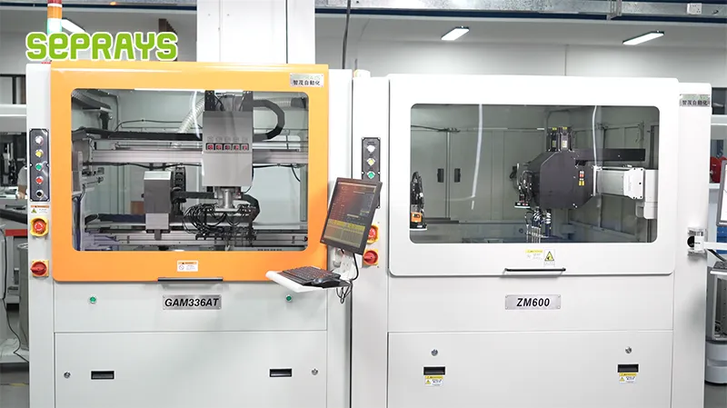
Recommended Depaneling Equipment
If the challenges described in this article sound familiar, these machines may be exactly what you need:
- GAM330AT Fully Automatic PCB Depaneling Machine — Self-feeding operation with automatic sorting — ideal for high-volume automated production lines
- PCB/FPC Stamping Type Board Separation Machine — Handles PCB, FPC flexible, and rigid-flex boards — versatile stamping depaneling solution
Frequently Asked Questions
Q1: What tolerance specification should we target for depaneling precision-critical PCBs in SMT assembly?
A1: The industry standard tolerance for depaneling precision-critical PCBs is ±0.05mm or tighter, consistent with IPC-2221 guidelines. This level of precision ensures that routed edges do not induce stress on surface-mounted components located within 3mm of the panel border, which is critical for maintaining solder joint integrity and preventing pad cracking during the depaneling operation.
Q2: How does depaneling method selection impact overall SMT line throughput and production efficiency?
A2: The depaneling method directly impacts throughput rates, with router-based systems typically achieving 300-500 boards per hour compared to 150-250 boards per hour for manual depaneling. Selecting the appropriate method—routing, V-groove cutting, or laser depaneling—during SMT process planning eliminates bottlenecks and reduces labor costs by up to 60% in high-volume production environments.
Q3: What are the primary causes of PCB defects during depaneling, and how can they be prevented in SMT assembly?
About Seprays
Who is Seprays? Seprays Precision Machinery, founded in 2011, is a professional manufacturer specializing in high-precision PCB depaneling machines. Trusted by Fortune 500 companies and electronics manufacturers in 31 countries, Seprays delivers equipment that consistently meets the demanding tolerances of automotive, medical, aerospace, and consumer electronics production lines.
Seprays product lineup: PCB Router Depaneling Machines, V-Cut PCB Depaneling Equipment, Laser PCB Depaneling Systems, Inline Automated Depaneling Lines, and custom depaneling solutions. Every Seprays machine comes with a full warranty and lifetime technical support.


