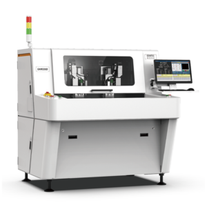

Rigid-flex PCBs combine FR-4 with polyimide flex layers bonded by acrylic or epoxy adhesives. The interface between rigid and flex is the most common failure point during depaneling — a router bit that runs too fast tears the adhesive; too slow overheats the polyimide.
1. Why Rigid-Flex Is Different From Plain FR-4
A typical 4-layer rigid-flex stack-up is 0.2 mm polyimide flex + 0.4 mm FR-4 rigid + 0.2 mm flex, with acrylic adhesive layers in between. The flex sections bend to ±180° in operation. After SMT assembly, the entire panel must be depaneled without:
- Peeling the polyimide from the FR-4 at the rigid-flex interface
- Cutting too close to the bend line where flex fatigue concentrates
- Generating heat that warps the acrylic adhesive
- Inducing micro-cracks in the rigid section through vibration
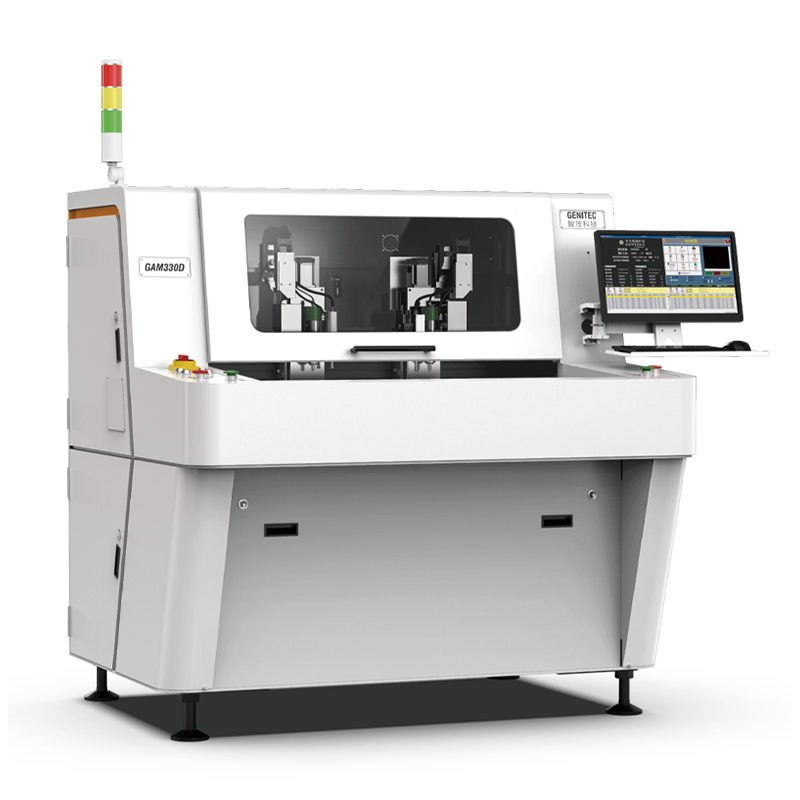
A standard FR-4 PCB router machine running 60,000 RPM will tear the polyimide-adhesive interface within 5 mm of the rigid-flex transition. The right tool is a rigid-flex router running a slower spindle (typically 30K–45K RPM), a sharp diamond-cut bit, and a controlled dust extraction path that doesn’t suck heat into the cut zone.
2. Spindle Speed and Bit Selection
The combination matters:
- Spindle: 30,000–45,000 RPM (slower than FR-4)
- Bit: 0.8–1.0 mm tungsten carbide, single-flute, diamond-coated; flute count of 1 (not 2) reduces chip load
- Feed rate: 50–100 mm/min for rigid sections; 30–60 mm/min across the rigid-flex transition
- Cut depth per pass: 0.2–0.5 mm — multiple shallow passes prevent heat buildup
For high-volume rigid-flex production, a PCB router machine with programmable Z-axis depth control and per-segment feed override is essential.
3. The 3 mm Rule Around the Bend Line
Industry-standard design rule: keep router cuts at least 3.0 mm away from the bend line of any flex section. Inside that 3 mm buffer zone, the cut path must run parallel to the bend direction, not perpendicular, to avoid scoring the polyimide where it folds.
Most rigid-flex routers on the market in 2026 — including the Seprays GAM-RF series — accept a cut-path polygon directly from the customer’s CAD/ODB++ export and automatically maintain the 3 mm buffer via a software rule. The PCB router machine then validates the path before cutting and warns the operator if any segment violates the buffer.
4. Vacuum Fixturing for Thin Rigid-Flex
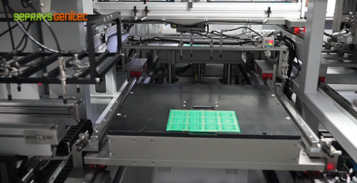
Rigid-flex panels flex under their own weight above 100 mm × 75 mm — and a router bit pushing laterally displaces a non-fixtured panel. The fixture must:
- Apply uniform vacuum pressure across the entire panel (not just the rigid sections)
- Have soft silicone gaskets that conform to the flex layer without crushing it
- Expose the cut zone while holding the surrounding 10 mm in place
A poorly designed fixture is the #1 cause of rigid-flex router defects in the field. If your PCB router machine vendor offers only a flat FR-4 vacuum bed, the cycle time will be 50% longer (operator must re-position the panel for each pass) and the yield will be lower.
5. Comparing Router vs Laser for Rigid-Flex
For very thin flex (below 100 µm polyimide, no FR-4 backing), a UV laser depaneling system is faster and produces no mechanical stress. For rigid-flex panels where the rigid sections are still present, a router is more cost-effective and faster.
The crossover: if the flex section is below 50 µm and the panel includes micro-vias in the flex layer, route the rigid sections with the router and route the flex sections with a UV laser. Most modern PCB router machines can be paired with a laser station in a hybrid cell.
6. Common Defects and Process Windows
Defect #1 — adhesive squeeze-out at the cut edge: usually a sign the bit is dull or the feed is too slow. Replace bit; raise feed by 20%.
Defect #2 — copper lift at the rigid-flex interface: bit too close to copper pad. Increase clearance or change bit direction relative to pad.
Defect #3 — polyimide whitening: bit running too hot. Reduce RPM by 10K, add a 2-second pause every 50 mm of cut.
7. Capacity Planning
A typical inline PCB router machine processes 200–400 rigid-flex boards per shift (8 hr) depending on cut-path complexity. For medical wearables or aerospace harnesses, the throughput is usually 60–150 boards/shift because the cut paths are longer.
If you are scaling rigid-flex production above 5,000 boards/month, invest in an automated load/unload conveyor and an inline AOI station immediately after the router. The downstream cost of catching a misalignment at AOI is 5× lower than at final test.
8. Tooling Cost Reference
Diamond-coated 0.8 mm bits for rigid-flex cost $20–35 each and last 40–80 m of cut on FR-4, 15–25 m on polyimide. Plan $0.10–0.30 in bit consumption per board at typical cut path lengths.
For a deeper dive into how a PCB router machine handles other specialty laminates, see our PCB router machine overview and our guide to laser depaneling for flex circuits.
About Seprays Precision Machinery

Founded in 1993, Seprays Precision Machinery has over 30 years of expertise in PCB depaneling solutions. With two manufacturing facilities totaling 26,000 m², 9 service centers across China, and clients in 31 countries — including Foxconn, Flex, Luxshare, Bosch, and CRRC — Seprays delivers equipment that consistently meets the demanding tolerances of automotive, medical, aerospace, and consumer electronics production lines.
Certifications: ISO 9001, ISO 14001, ISO 45001, CE. Patents: 100+. Need a customized depaneling solution or want to discuss your specific production requirements? Our technical team is ready to help. Contact: jimmy@seprays.com
FAQ
Q1: What spindle speed is right for FR-4 PCB routing?
A: 40,000–60,000 RPM is the standard range for FR-4. Lower speeds cause tearing; higher speeds require diamond-coated bits.
Q2: How often should I replace the spindle on a PCB router machine?
A: Every 25,000 hours in a clean environment, 12,000–15,000 hours with average dust management, 8,000 hours if dust extraction is poor.
Q3: Can a PCB router machine cut ceramic PCBs?
A: Yes, with diamond-coated bits and reduced feed rates (30–60 mm/min). For ultra-thin ceramics, consider laser depaneling instead.
Q4: What is the typical bit life on FR-4?
A: 30–80 m of cut per bit, depending on stack-up thickness and RPM. Plan $0.10–0.30 in bit cost per board.
Q5: How do I know if my spindle bearings are wearing?
A: Audible noise, vibration above 4 mm/s RMS, or degraded cut quality that doesn’t improve with bit replacement. Plan a spindle swap.