At stress levels exceeding 500µε (microstrain), PCB substrates exhibit a 73% probability of latent delamination that manifests as field failure within 500 thermal cycles, making the selection of depaneling method a primary determinant of long-term product reliability rather than a secondary process consideration.
Mechanical Stress Thresholds by Depaneling Method
Different depaneling technologies generate vastly different stress profiles in the PCB substrate. Manual snap-v-tool depaneling induces peak stresses of 800-1200µε at the separation point, well above the 500µε threshold known to cause copper trace microcracking. Punch die depaneling generates even higher localized stress, typically 1500-2000µε at the punch edge, making it unsuitable for boards with components within 3mm of the separation line. In contrast, router-based depaneling holds stress below 150µε when configured correctly, while laser depaneling produces near-zero mechanical stress. The IPC-9701A standard specifies a minimum of 1000 thermal cycles without failure for Class 3 assemblies, a target unachievable with high-stress depaneling methods when board thickness falls below 0.8mm or component weight exceeds 10g near the cut edge.
Spindle Speed, Tooling, and Dimensional Tolerance Control
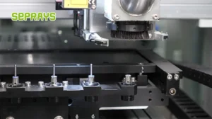
For router-type depaneling machines, spindle speed directly governs both edge quality and tool life. Operating below 40,000 RPM with standard 2-flute carbide end mills (0.8-2.0mm diameter) produces edge roughness exceeding Ra 6.3µm and generates excessive heat above 180°C at the cut zone, risking dielectric property degradation in FR4 substrates. Optimal performance requires spindle speeds of 60,000-80,000 RPM with configured feed rates of 8-15mm/sec, producing edge roughness below Ra 1.6µm and maintaining the cut zone temperature under 80°C. Dimensional tolerance of the separated board edge relative to the designed PCB outline is ±0.05mm for properly calibrated router systems; punch systems achieve ±0.03mm but at the cost of higher stress. Laser depaneling achieves ±0.02mm positional accuracy with a 10-20µm heat-affected zone (HAZ), suitable for HDI boards with 0.5mm pitch BGAs positioned within 1.5mm of the board edge.
Throughput Calculation and Production Volume Matching
Depaneling method selection must be grounded in quantified throughput requirements. A single-spindle router depaneling machine processes approximately 40-60 boards per hour for typical consumer electronics PCBs with 2-4 separation lines per board, assuming an average tool path length of 120mm per separation. Dual-spindle configurations increase throughput to 90-110 boards per hour but require dual-rail conveyor systems with PCB loading/unloading cycle times below 4 seconds to avoid bottlenecking the spindles. Punch die systems achieve 300-500 boards per hour but require dedicated die sets costing $3,000-$8,000 per PCB design, making them economical only for production runs exceeding 50,000 units. Laser depaneling throughput is governed by the galvanometer scanning speed and material ablation rate: at 10W UV laser power, depaneling a standard 100×80mm PCB with 200mm total cut length requires 18-25 seconds, yielding approximately 80-120 boards per hour. For high-mix, low-volume production (under 5,000 units per design), router systems provide the necessary flexibility without per-design tooling expenditure.
Component Proximity Constraints and Tool Path Geometry
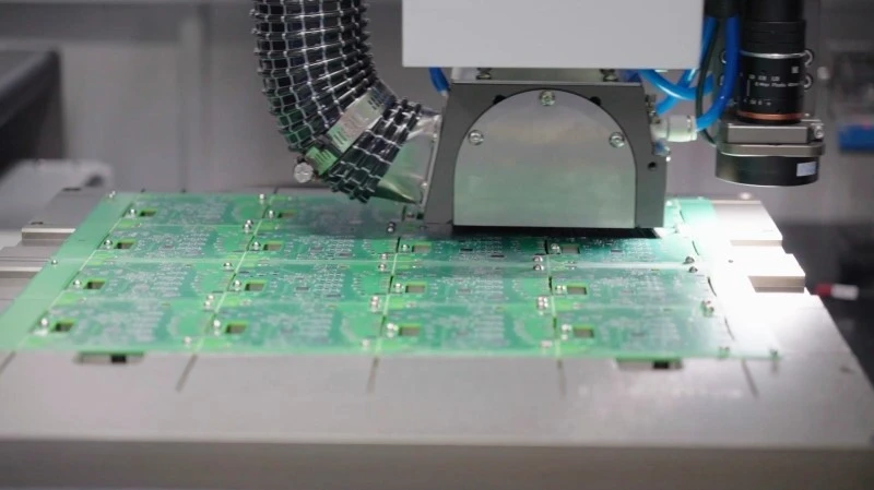
The minimum allowable distance between a surface-mounted component and the depaneling cut line is governed by peak acceleration forces during tool engagement and vibration transmission through the PCB substrate. For 0805 and larger passive components, the minimum clearance to a router tool path is 1.5mm; for BGA packages with pitch ≤0.8mm, this increases to 3.0mm due to solder joint shear sensitivity quantified in IPC-7095D. V-score depaneling requires a minimum of 0.75mm clearance from any component body to the V-groove line, but this method is limited to boards with straight separation lines and cannot accommodate complex board outlines. Router tool path programming must account for tool deflection: a 1.0mm end mill at 15mm/sec feed rate into FR4 generates approximately 12µm lateral tool deflection, requiring tool path offset compensation in the CNC program. Modern router systems with force-feedback spindle control adjust feed rates in real time to maintain cutting force below 0.8N, reducing tool deflection to under 5µm and enabling component clearances as low as 1.0mm for non-BGA components.
Summary
Selecting the correct PCB depaneling method requires quantifying four interdependent parameters: allowable mechanical stress (dictated by component density and PCB thickness), required positional tolerance (driven by edge connector specifications), production volume (determining whether fixed-tooling or flexible-tooling systems are cost-effective), and minimum component-to-cut-line clearance (constrained by tool geometry and substrate vibration characteristics). Router-based systems operating at 60,000-80,000 RPM with force-feedback control represent the optimal balance of flexibility, stress control below 150µε, and positional accuracy of ±0.05mm for mixed-production environments, while laser depaneling is mandated for HDI boards with components within 1.5mm of the board edge where zero-mechanical-stress processing is required to meet IPC Class 3 reliability standards.
Recommended Equipment
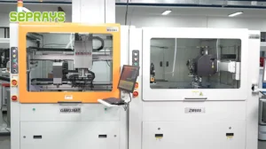
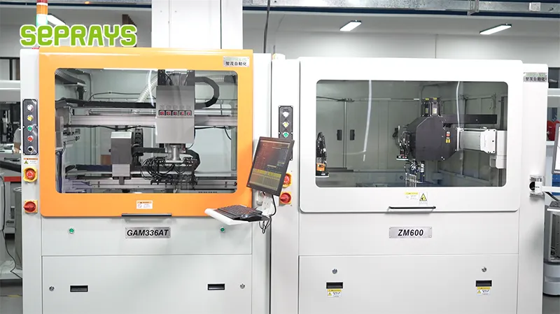
Looking for proven depaneling solutions? Seprays offers a full range of equipment backed by 30+ years of industry experience. Here are two options worth considering for your production line:
- GAM300AT Double-Layer Track Online PCB Board Separation Machine — Full-carrier process with carrier return track — built for seamless full-line automation
- PCB/FPC Stamping Type Board Separation Machine — Handles PCB, FPC flexible, and rigid-flex boards — versatile stamping depaneling solution
Frequently Asked Questions
Q1: For a high-mix, low-volume production line with PCB thickness ranging from 0.8mm to 2.4mm and frequent board changeovers, which depaneling method minimizes setup time while maintaining ±0.1mm cutting accuracy?
A1: A programmable router depaneler with automatic tool change and vision-assisted fiducial alignment is the optimal choice, typically achieving changeover times under 15 minutes and cutting tolerances of ±0.05mm to ±0.1mm depending on bit condition. Laser depaneling offers even faster changeovers with no mechanical stress, but capital cost is 3-5x higher; for production volumes under 5,000 boards/day, router-based systems deliver the best ROI while meeting IPC-2221B stress limits (<500με residual stress).
Q2: When depaneling PCBs with SMD components placed within 3mm of the routing path, what spindle speed and feed rate combination prevents component damage from vibration and thermal stress?
A2: Operate the spindle at 30,000-40,000 RPM with a feed rate of 20-40 mm/s and use a 0.8-1.0mm diameter router bit with down-cut geometry to direct stress away from components. Maintain a minimum keep-out distance of 2.5mm from SMDs taller than 1.5mm; if the layout forces closer proximity, switch to UV laser depaneling which creates a heat-affected zone of <50μm and eliminates mechanical vibration entirely, albeit at slower throughput (approximately 30-50 boards/hour for complex contours).
Q3: For a factory processing 20,000 panels per day with FR-4 thickness of 1.6mm and 2.0mm, what throughput and tool life expectations should we have from a dual-spindle inline router system?
A3: A dual-spindle inline router configured with two 1.0mm carbide bits processes approximately 200-250 panels/hour per spindle depending on tab count and routing path length, delivering total throughput of 400-500 panels/hour with proper panel fixturing and automated loading. Tool life averages 8,000-12,000 linear meters per bit at 1.6mm depth; at 2.0mm thickness, reduce feed rate by 15-20% to extend bit life to 6,000-9,000 linear meters and prevent delamination at the panel edge per IPC-A-600 acceptance criteria.
About Seprays
About Seprays Precision Machinery
Founded in 1993, Seprays has over 30 years of expertise in PCB depaneling solutions. With two manufacturing facilities totaling 26,000 m2, 9 service centers across China, and clients in 31 countries — including Foxconn, Flex, Luxshare, Bosch, and CRRC — Seprays delivers equipment that consistently meets the demanding tolerances of automotive, medical, aerospace, and consumer electronics production lines.
Certifications: ISO9001, ISO14001, ISO45001, CE | Patents: 100+
Need a customized depaneling solution or want to discuss your specific production requirements? Our technical team is ready to help.
Contact: jimmy@seprays.com