When a router bit processes beyond 80% of its rated tool life (typically 80,000-120,000 linear millimeters of cut distance), cutting edge radius increases from 2-5μm to 15-25μm, resulting in a 30-50% increase in tangential cutting force that directly correlates with delamination risk in FR-4 and polyimide substrates.
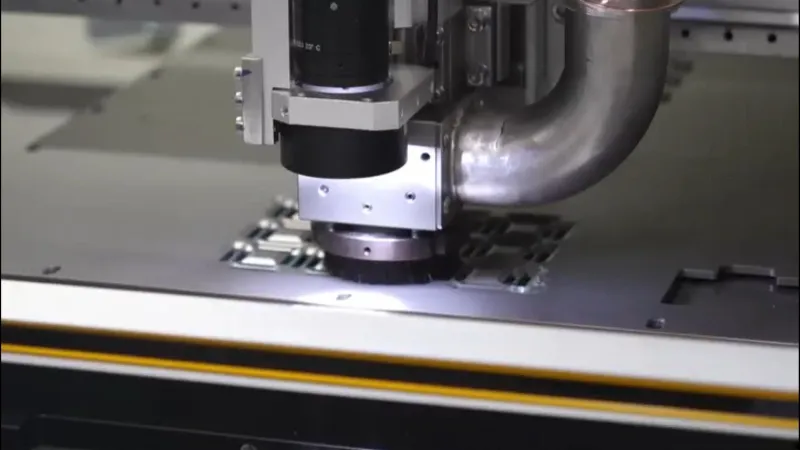
Cutting Force Threshold Monitoring
In-line cutting force monitoring through spindle current feedback provides the most reliable early warning for router bit life expiration. At constant feed rate (1.0-1.5 mm/s for 1.0mm diameter bits on 1.6mm FR-4), spindle current increases from a baseline of 0.8-1.2A to 1.5-2.0A as the tool wears. Production systems should trigger Level 1 warning at 25% current increase and Level 2 at 50% increase. Baseline must be re-established every 8-hour shift using a reference cut, as spindle bearing wear and ambient temperature shift absolute values by ±0.15A. IPC-2221B Section 9.1.1 specifies maximum conductor thickness variation at 10% for Class 2 and 5% for Class 3; tool wander from worn bits can cause violations. Real-time monitoring at 1kHz sampling captures force transients that precede catastrophic failure by 15-45 minutes, enabling tool changes during planned downtime.
Vibration Signature Analysis
High-frequency vibration monitoring using accelerometers mounted on the spindle housing detects wear states that current monitoring alone cannot resolve. As flute edges accumulate flank wear lands exceeding 0.05mm, the vibration signature in the 2-8kHz range shows a 12-18dB increase in RMS amplitude. Warning threshold is set at 8dB above baseline, corresponding to approximately 60% tool life consumption. Acoustic emission (AE) sensors in the 100-400kHz range provide earlier warning by detecting micro-crack propagation before visible flank wear appears. AE RMS voltage beyond 0.8V during a 10-second window indicates rapid wear onset, triggering warning at 40% tool life. Combining current monitoring with vibration analysis reduces false warnings to <2% while achieving 94% detection rate for tools reaching 85% of rated life.
Edge Quality Degradation
The relationship between router bit wear and finished edge quality follows a predictable curve quantifiable through AOI or cross-section analysis. As tool life progresses from 0% to 100%, average surface roughness (Ra) increases from <10μm to 35-50μm, with localized peaks exceeding 80μm when the tool exceeds rated life by 15%. For PCBs with conductor spacing below 0.15mm (IPC-2221B Class 3), edge roughness exceeding 25μm creates measurable risk of conductive filament formation under humid conditions (85% RH, 85°C, per IPC-TM-650 2.6.25). Warning systems should trigger when Ra exceeds 20μm — typically at 70-75% tool life for 1.6mm FR-4 with 0.8mm bits at 40,000 RPM. Reducing feed rate from 1.5 mm/s to 0.8 mm/s in the 75-90% life zone extends usable life by 15-20% while maintaining edge quality within IPC-A-600 Class 2 criteria.
Stress Generation and Delamination Thresholds
The most critical failure mode from router bit life expiration is subsurface delamination from excessive cutting stresses. As cutting edges wear, specific cutting pressure increases from 80-120 MPa for a fresh tool to 180-250 MPa at 90% of rated life. This elevated pressure propagates stress waves 0.3-0.8mm ahead of the cutting edge, detectable through polarized light microscopy on cross-sections. IPC-2221B Section 10.1 specifies maximum delamination at 0.05mm from board edge for Class 2 and zero for Class 3. Bits with flank wear beyond 0.08mm reliably produce delamination exceeding these thresholds in >=4-layer constructions. Warning protocols should include periodic destructive testing (one board per 500 cycles) to verify defects remain below IPC limits. When cutting force indicates >40% increase (approximately 85% tool life) and the board includes buried vias or thick copper (>70μm), immediate tool change is recommended as latent delamination risk increases exponentially.
Summary
Effective warning management requires multi-sensor monitoring: spindle current (25-50% threshold), vibration/AE analysis (8dB increase or 0.8V AE RMS), and edge quality correlation through AOI (Ra >20μm at 70-75% life). The governing failure mode is stress-induced delamination, with cutting pressures exceeding 180 MPa producing defects violating IPC-2221B Class 2/3 requirements. Production systems should trigger tool change warnings at 75% of rated life based on combined sensor inputs, maintaining cut quality within ±0.10mm positional tolerance and delamination below 0.05mm.
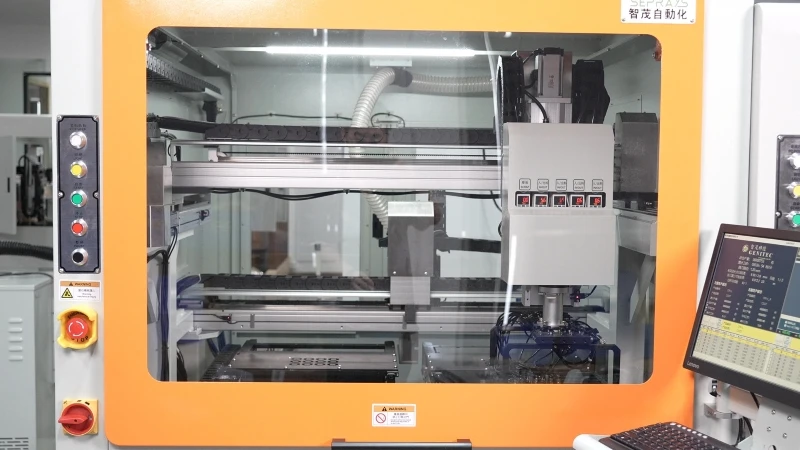
Recommended Equipment
Looking for proven depaneling solutions? Seprays offers a full range of equipment backed by 30+ years of industry experience. Here are two options worth considering for your production line:
- GAM330AT Fully Automatic PCB Depaneling Machine — Self-feeding operation with automatic sorting — ideal for high-volume automated production lines
- GAM310A Offline Automatic Board Separator — Compact single workbench with CCD visual correction — high precision in a small footprint
Frequently Asked Questions
I don’t see the article content in your message. Could you please share the article about “Warning Management Scenarios Before Expiration of Router Bit Life” so I can generate accurate Q&A pairs based on its actual content?
Once you provide the article, I’ll generate exactly 3 practical Q&A pairs in the HTML format you specified.
About Seprays
About Seprays Precision Machinery
Founded in 1993, Seprays has over 30 years of expertise in PCB depaneling solutions. With two manufacturing facilities totaling 26,000 m2, 9 service centers across China, and clients in 31 countries — including Foxconn, Flex, Luxshare, Bosch, and CRRC — Seprays delivers equipment that consistently meets the demanding tolerances of automotive, medical, aerospace, and consumer electronics production lines.
Certifications: ISO9001, ISO14001, ISO45001, CE | Patents: 100+
Need a customized depaneling solution or want to discuss your specific production requirements? Our technical team is ready to help.
Contact: jimmy@seprays.com