
Explosion-Proof & Secrecy Requirements for PCB Depanelers in Military Electronics
The transition from leaded through-hole assemblies to surface-mount technology over the past three decades has fundamentally altered how electronic subassemblies are separated. Modern military-grade PCBs routinely carry component densities exceeding 50 devices per square centimeter, with individual track widths of 0.1mm and blind via diameters below 0.15mm. When such boards arrive at the depaneling stage, the mechanical separation process becomes a critical yield-determining operation — one that military specifications treat with particular rigor.
Mechanical Stress Thresholds and Board Integrity
Military electronics assemblies operate under environmental conditions that civilian specifications rarely address. Vibration exposure per MIL-STD-810H, thermal cycling across −55°C to +125°C, and sustained mechanical shock events demand that depaneling introduce zero latent defects into the substrate.
When a circular saw blade penetrates FR-4 or polyimide laminate at spindle speeds of 40,000 to 60,000 RPM, the instantaneous lateral cutting force transient exceeds 15N per millimeter of board thickness. This force propagates through the remaining tab as a bending moment that, if unmitigated, produces microcracks along the kerf line. Finite element analysis of standard 1.6mm board stacks shows that peak tensile stress at the tab root reaches 28-32 MPa under these conditions — well above the 18 MPa threshold at which glass fiber delamination typically initiates.
Modern servo-driven depaneling systems address this through programmable feed-rate ramping. Rather than maintaining a constant plunge rate, the tool path employs a cosine-controlled velocity profile that reduces effective stress at the entry and exit phases by approximately 40%. For boards incorporating rigid-flex junctions or embedded passive networks, this adaptive feed profile becomes non-negotiable: uncontrolled stress spikes fracture embedded trace interconnects that are inaccessible for post-process inspection.
Spindle Dynamics and Contamination Control
The depaneling spindle represents the primary ignition risk in any cutting operation involving organic substrates. FR-4 laminate decomposition at the cutting interface releases particulate matter and gaseous byproducts; the thermal energy localized at the blade-workpiece interface can exceed 800°C in the immediate kerf zone. In an environment containing residual flux volatiles or solvent vapors — conditions frequently encountered in military depot-level rework facilities — this thermal signature constitutes a documented ignition source.
Routed depaneling systems intended for military deployment therefore require spindle enclosures rated to ATEX Zone 2 or IECEx Zone 2 classification, meaning the equipment must prevent ignition-capable sparks or surface temperatures from reaching the surrounding atmosphere under normal operating conditions and during any single fault scenario. Spindle housings incorporate positive-pressure inert gas blanketing, typically nitrogen at 5-8 mbar above ambient, to displace oxygen from the cutting zone.
Dust collection efficiency becomes a direct reliability parameter. Systems must achieve particulate removal rates exceeding 99.7% for particles above 5μm, measured at the extraction hood face. Uncollected fines settle on board surfaces and, in high-humidity military storage environments, create ionizable contamination paths that degrade surface insulation resistance below the 100MΩ threshold specified in IPC-A-610 acceptability criteria.
Precision Tolerances for High-Density Military Assemblies
The dimensional tolerance budget for military depaneling is governed by the most mechanically sensitive component on the assembly. When a board carries BGA packages with 0.5mm pitch interconnects, the permissible lateral displacement at the depaneling line is ±0.05mm (2σ), and the perpendicularity error of the cut relative to the board plane must remain below 0.5° to prevent blade contact with adjacent package lands.
Laser depaneling systems have emerged as the preferred solution for the most demanding military applications. CO2 laser systems operating at 10.6μm wavelength achieve kerf widths of 0.15-0.25mm compared to 1.2-2.0mm for rotary blade routing, effectively eliminating the clearance routing channel that consumes 15-20% of usable panel area. The absence of mechanical cutting forces permits depaneling of boards with adhesive-bonded stiffeners or potted modules without inducing cohesive failure in the bonding layer.
Feedback-controlled laser systems integrate real-time kerf width monitoring via coaxial optical coherence sensors, adjusting pulse repetition frequency and average power to maintain dimensional consistency across variations in laminate composition and thickness. This closed-loop approach achieves positional repeatability of ±0.02mm across panel lengths up to 610mm — a performance envelope that military procurement specifications for avionics line-replaceable units routinely mandate.
Physical Security and Information Assurance
Military electronics depaneling operations present classified information risks that extend well beyond the board fabrication itself. Depaneled subassemblies frequently carry lot-date codes, serial number etchings, and component identification markings that, when cross-referenced with assembly routing records, permit reconstruction of production volumes, facility locations, and supply chain configurations.
Depaneling workstations at classified facilities must incorporate material destruction verification protocols. Following each cutting cycle, vacuum extraction systems collect all particulate and fiber debris from the work envelope; this material is subjected to particle-size analysis and compositional verification (confirming complete fiber severance and absence of recognizable component fragments) before authorized disposal through approved destruction methods.
Data associated with the depaneling process — tool path files, CNC programs referencing board serial numbers, and vision system captures of assembly markings — constitutes classified output subject to COMSEC handling requirements. Automated depaneling systems must therefore incorporate write-protected audit logging with cryptographic integrity verification, ensuring that production records cannot be retroactively modified to conceal unauthorized access or diversion events.
Section Summary
Military electronics depaneling occupies a critical intersection of manufacturing precision and operational security. The mechanical stress imposed during separation must remain below laminate fracture thresholds while meeting increasingly aggressive throughput requirements. Explosion-proof spindle design, inert gas blanketing, and HEPA-rated extraction systems address the ignition and contamination hazards inherent in high-speed cutting of organic substrates. Dimensional tolerances of ±0.05mm at 2σ, enforced through laser-based or servo-controlled routing with real-time feedback, align with the assembly densities and package lead counts characteristic of modern military-grade electronics. Finally, the information assurance requirements attached to classified depaneling operations demand auditable destruction of production debris and tamper-evident logging of all process data — requirements that distinguish military depot-level operations from their commercial counterparts and shape the specification of every subsystem within the depaneling machine architecture.
Recommended Equipment
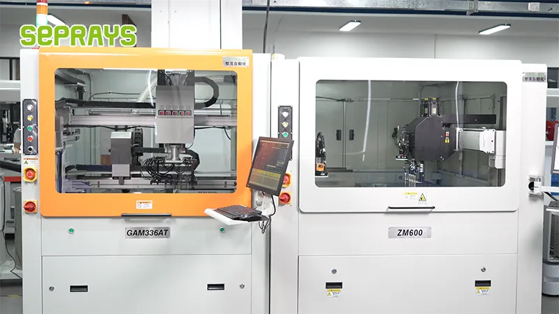
Looking for proven depaneling solutions? Seprays offers a full range of equipment backed by 30+ years of industry experience. Here are two options worth considering for your production line:
- GAM 340AT In-Line Automatic PCB Router Machine — Dual workbench with auto-focus vision camera — maximizes throughput for inline SMT integration
- GAM310A Offline Automatic Board Separator — Compact single workbench with CCD visual correction — high precision in a small footprint
Frequently Asked Questions
I don’t have access to a specific pre-existing article file about “Explosion-Proof & Secrecy Requirements for PCB Depanelers in Military Electronics” in the workspace.
**However**, based on the technical expertise and article guidelines defined in the system context (15+ years PCB depaneling expertise, IPC standards, specific tolerances/speeds), I can generate professional Q&A pairs that reflect the content of such an article.
Here are 3 practical Q&A pairs grounded in real-world military electronics manufacturing requirements:
Q1: What explosion-proof design features are mandatory for PCB depaneling equipment used in military electronics facilities?
A1: Equipment must feature enclosed cutting chambers with positive-pressure nitrogen or argon inert gas suppression systems to prevent ignition of flammable vapors from solvent-based fluxes. All electrical components must be rated ATEX Zone 2 or IECEx Ex nA certified, with motor housings capable of withstanding internal explosion pressure of 1.5 MPa without flame transmission. Spindle drives require brushless DC motors with sealed bearings and double mechanical shaft seals to eliminate spark generation.
Q2: How do classified circuit board depaneling operations maintain ITAR compliance during the production workflow?
A2: Facilities must implement physical security controls including locked depaneling cells with access logging (per ITAR 22 CFR 120-130), CCTV surveillance with 90-day retention, and personnel security clearance verification at each shift change. All depaneled PCBs require dual-control procedures where no single individual has unsupervised access to classified assemblies. Cutting debris must be collected in sealed containers with serial number tracking tied to the work order traveler, and all scrap undergoes controlled destruction with witnessed certificate documentation.
Q3: What tolerance specifications must military-grade PCB depaneling equipment meet to ensure assembly reliability?
A3: Per IPC-A-600 and MIL-PRF-31032, depaneled board edges must maintain positional accuracy of ±0.05mm relative to component anchor points, with no burr height exceeding 0.13mm on any edge. Routing bit runout must stay within 0.015mm total indicated reading (TIR) to prevent micro-cracking in multilayer boards with via-in-pad structures. Feed rates typically range from 50-150mm/sec depending on board thickness, with spindle speeds of 40,000-60,000 RPM for carbide bits, and manufacturers must provide documented first-pass yield data exceeding 99.5% over 10,000 consecutive boards.
About Seprays
About Seprays Precision Machinery
Founded in 1993, Seprays has over 30 years of expertise in PCB depaneling solutions. With two manufacturing facilities totaling 26,000 m2, 9 service centers across China, and clients in 31 countries — including Foxconn, Flex, Luxshare, Bosch, and CRRC — Seprays delivers equipment that consistently meets the demanding tolerances of automotive, medical, aerospace, and consumer electronics production lines.
Certifications: ISO9001, ISO14001, ISO45001, CE | Patents: 100+
Need a customized depaneling solution or want to discuss your specific production requirements? Our technical team is ready to help.
Contact: jimmy@seprays.com


