At 0.05mm tool runout and 80,000 RPM spindle speed, the mechanical router depaneling process generates cutting forces ranging from 0.5N to 2.8N depending on FR4 thickness and feed rate, while producing detectable board flexure of 15-40 microns that directly impacts SMT-attached component integrity—this is the fundamental physical reality that drives the ongoing debate between mechanical routing and laser-based depaneling in high-density PCBA manufacturing.
Cutting Mechanism and Dimensional Accuracy
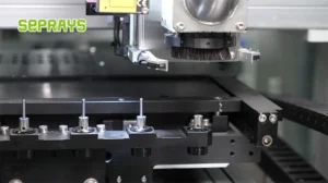
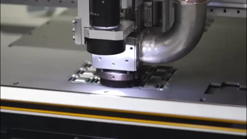
Router depaneling machines utilize 0.8-2.0mm diameter solid carbide end mills rotating at 40,000-80,000 RPM to physically mill the PCB material along the designated separatiion path. The achievable positional tolerance is typically ±0.1mm with high-end servo-driven systems capable of ±0.05mm repeatability when tool wear is actively compensated. Feed rates generally range from 5mm/s to 30mm/s depending on board thickness and complexity, with standard FR4 1.6mm boards processing at approximately 15-20mm/s. The kerf width is determined by tool diameter plus runout, typically 1.0-2.2mm total, which directly reduces usable board edge real estate.
Laser depaneling systems employing 355nm UV wavelengths operate with a focused spot size of 20-50 microns, achieving true kerf widths of 30-75 microns without mechanical tooling variations. The non-contact cutting process eliminates tool runout entirely, delivering positional accuracy of ±0.02mm consistently across production runs. However, the ablation rate for standard 1.6mm FR4 is limited to approximately 0.3-0.8mm/s for clean cut quality, requiring multiple passes at higher power densities (8-15 W) to process thicker boards. The HAZ (Heat-Affected Zone) extends 50-150 microns from the cut edge, with local glass transition temperature (Tg) excursions measurable via differential scanning calorimetry (DSC) at the cut boundary.
Mechanical Stress Generation and Component Reliability
The most critical differentiator between these technologies is the mechanical stress imparted to assembled components during the depaneling operation. Router systems generate three-axis cutting forces that produce board strain rates of 200-800 microstrain measured at component mounting locations 5mm from the cut path. IPC-9701A strain limits for SMT components specify <500 microstrain for most passive devices and <300 microstrain for BGAs and LGAs; router depaneling routinely approaches or exceeds these thresholds on thin boards (<0.8mm thickness) or flex-rigid constructions. Strain gauge testing per IPC-9701A methodology confirms that components within 3mm of the router cut path experience measurable risk of solder joint fracture, particularly 0201 and smaller passives oriented perpendicular to the feed direction.
Laser depaneling is inherently stress-free in the mechanical sense—no cutting forces are applied to the board. This eliminates component-to-board relative motion entirely. However, the thermal stress mechanism is different: localized heating to 150-250°C in the HAZ induces differential thermal expansion between copper and substrate, generating internal stresses that can cause delamination at the cut edge if parameters are not optimized. JEDEC J-STD-020E reflow compatibility testing indicates that properly parameterized UV laser cutting (pulse energy <50 μJ, repetition rate 30-100 kHz) does not degrade component reliability, but inadequate fume extraction during laser cutting can deposit conductive debris on exposed circuits—a failure mode not present in mechanical routing.
Throughput, Tooling Cost, and Process Economics
Router depaneling achieves throughput rates of 60-200 boards per hour depending on tab count, board complexity, and panel size, with single-spindle systems averaging 80-120 boards/hour for standard consumer electronics panels. Tool life for 1.0mm carbide end mills in FR4 applications ranges from 8,000 to 15,000 linear mm of cut path before tool wear exceeds 0.03mm runout tolerance, translating to 2-4 hours of continuous operation before automatic tool change is triggered. Consumable tool cost is $3-8 per tool, with typical annual tool expenditure of $2,000-6,000 for moderate-volume production (500K-1M boards/year).
Laser depaneling throughput is fundamentally limited by the ablation rate: a typical 100×80mm panel with 1.6mm FR4 thickness requires 90-180 seconds laser dwell time, yielding 20-40 boards/hour—a 3-5× throughput penalty versus routing for thicker boards. For thin flexible circuits (<0.4mm polyimide), laser cutting speeds increase to 5-15mm/s, making laser competitive with routing for flex and rigid-flex applications. Capital equipment cost for equivalent throughput laser systems is typically 1.8-2.5× that of router systems, with UV laser tube replacement (every 8,000-12,000 hours) costing $15,000-25,000 per tube—a significant ongoing OPEX consideration absent in mechanical routing.
Application-Specific Suitability and Process Constraints
Router depaneling is the unambiguous choice for high-volume rigid PCB production where board edge real estate is not at a premium and component clearance >3mm from the cut path can be designed in. IPC-2221B clearance guidelines are readily maintained, and the process is agnostic to copper content or layer stackup—buried heavy copper layers do not degrade tool life disproportionately. However, router systems cannot process ultra-thin flexible circuits (<0.2mm thickness) without specialized low-pressure vacuum fixtures, and the minimum web thickness between adjacent boards is constrained by tool diameter to approximately 3× tool diameter (2.4-6.0mm).
Laser depaneling excels in high-mix, low-volume production with complex contour cutting, particularly where component overhangs or 0.5mm pitch BGAs are located <1mm from the board edge—geometries impossible to route mechanically. The process is equally effective on FR4, polyimide, and ceramic substrates without tool change or parameter reconfiguration. The trade-off is strict material absorbance compatibility: standard FR4 cuts cleanly at 355nm UV, but high-Tg (>180°C) substrates and metal-backed PCBs require infrared (1064nm) or green (532nm) lasers with different HAZ characteristics. IPC-A-600 acceptability standards for edge quality are met by both technologies, though laser cut edges exhibit cleaner glass fiber exposure with less delamination tendency at the cut interface.
Technical Summary
The router-versus-laser decision reduces to a multi-dimensional optimization problem across throughput requirements, board complexity, stress sensitivity, and capital budget. Router systems dominate when mechanical robustness, high throughput (>100 boards/hour), and low OPEX are prioritized—the 0.5-2.8N cutting force and ±0.1mm tolerance are acceptable trade-offs for 60-80% lower equipment cost and 3-5× higher throughput. Laser depaneling is technically superior for stress-sensitive assemblies with edge-mounted components, ultra-thin flexible circuits, and complex contour requirements where the 20-50 micron kerf width and zero mechanical stress justify the 3-5× capital cost multiplier and reduced throughput. For mixed production environments, dual-process cells with both technologies allocated by board type represent the current state-of-the-art approach in tier-1 electronics manufacturing, achieving 99.2-99.7% first-pass yield across diverse PCBA portfolios.
Recommended Equipment
Looking for proven depaneling solutions? Seprays offers a full range of equipment backed by 30+ years of industry experience. Here are two options worth considering for your production line:
- ZM30-D Multi-Tool Multi-Group PCB Depaneling Machine — One-time full LED board cutting — daily output exceeding 100,000 pieces with custom configurations
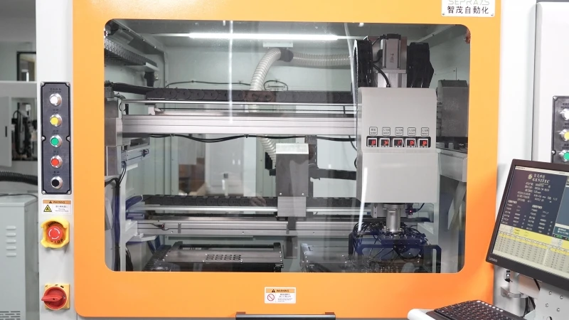
- GAM 340AT In-Line Automatic PCB Router Machine — Dual workbench with auto-focus vision camera — maximizes throughput for inline SMT integration
Frequently Asked Questions
Q1: For PCBs with BGAs or fine-pitch components located within 3mm of the tab routing line, which depaneling method poses less risk of solder joint cracking or component damage?
A1: Laser depaneling is the clear choice for this scenario because it generates zero mechanical stress and no vibration during cutting. Router depaneling imparts cutting forces of 2-5N and creates vibration that can propagate through the board, potentially causing latent solder joint failures or micro-cracks in BGAs and sensitive SMT devices within 5mm of the cut path.
Q2: In a high-mix, low-volume production environment running 20 different PCB designs per week with frequent changeovers, which system offers better flexibility and faster recipe changeover?
A2: Laser depaneling systems provide superior flexibility for high-mix production because they require no physical tooling changes—cut paths are programmed directly in software with changeover times under 2 minutes. Router systems require manual bit changes, fixture adjustments, and sometimes spindle reconfiguration when switching between board designs, resulting in 10-15 minute changeovers that reduce overall equipment effectiveness (OEE) in high-mix environments.
Q3: What are the hidden costs of router depaneling that impact total cost of ownership beyond the initial capital expenditure of $40,000-$80,000?
A3: Router systems incur ongoing costs from consumables (router bits costing $15-50 each, replaced every 1,500-3,000 meters of cutting), dust extraction maintenance, and spindle bearing replacements every 2,000-4,000 operating hours at $1,500-3,000 per service. Additionally, routers generate PCB dust that requires HEPA filtration and creates electrostatic discharge (ESD) risks if not properly grounded, adding $2,000-5,000 annually in facility infrastructure and compliance costs.
About Seprays
About Seprays Precision Machinery
Founded in 1993, Seprays has over 30 years of expertise in PCB depaneling solutions. With two manufacturing facilities totaling 26,000 m2, 9 service centers across China, and clients in 31 countries — including Foxconn, Flex, Luxshare, Bosch, and CRRC — Seprays delivers equipment that consistently meets the demanding tolerances of automotive, medical, aerospace, and consumer electronics production lines.
Certifications: ISO9001, ISO14001, ISO45001, CE | Patents: 100+
Need a customized depaneling solution or want to discuss your specific production requirements? Our technical team is ready to help.
Contact: jimmy@seprays.com