When depaneling PCBs with surface-mounted components as small as 01005 packages or BGAs with 0.3mm ball pitch, the mechanical stress generated by a poorly specified depaneling machine can exceed 150 MPa at the board edge—surpassing the fracture toughness of FR4 laminate and causing latent delamination that triggers field failures 3-6 months after deployment.
Spindle Speed and Cutting Tool Specifications
The rotational speed of the depaneling spindle directly determines edge finish quality and tool life. Production-grade depaneling machines specify spindle speeds ranging from 40,000 RPM for standard FR4 to 80,000 RPM for high-density polyimide and flexible rigid-flex boards. Below 30,000 RPM, tool chatter introduces edge roughness exceeding Ra 6.3 μm, which violates IPC-A-600 Class 2 edge finish criteria. Above 60,000 RPM on standard 1.6mm FR4, thermal buildup at the cutting interface can exceed 180°C, risking resin smear that partially bridges adjacent traces.
Tool collet runout must be specified at ≤0.005mm TIR (Total Indicator Reading). Runout above 0.01mm accelerates tool wear by a factor of 3× and introduces cyclic side-loading on the PCB edge that can cause micro-cracking in adjacent plated through-holes within 0.5mm of the board edge. The technical data sheet should explicitly state the runout measurement method—laser displacement sensor measurement at the tool tip is the only acceptable standard; dial indicator measurements at the collet nose are insufficient.
Dimensional Accuracy and Tolerance Control
Depaneling accuracy is specified as the cumulative positioning tolerance of the cutting head relative to the PCB datum. For standard SMT assemblies, the data sheet must guarantee ±0.05mm positional repeatability across the full X-Y travel range. When the application involves RF PCBs with edge-launched connectors where the board edge profile tolerance is ±0.1mm total, the depaneling machine must hold ±0.03mm to accommodate tool deflection compensation.
A critical often-overlooked parameter is Z-axis depth control. When depaneling scored boards (V-score), the residual web thickness after depaneling must be ≤0.13mm for 1.0mm core thickness, with a tolerance of +0.05/-0.00mm. If the Z-axis depth control is specified with ±0.1mm tolerance, the process window collapses—depaneling too deep fractures the opposing side V-groove; too shallow leaves excessive web material that requires secondary manual breaking, introducing uncontrolled flexural stress exceeding 200 MPa.
The data sheet should also specify linear encoder resolution. A machine using 1 μm resolution linear encoders can achieve consistent edge-to-feature distances of ±0.05mm; machines with 10 μm encoders exhibit batch-to-batch variation of ±0.15mm, which exceeds the IPC-2221 minimum electrical clearance for 250V circuits.
Feed Rate and Throughput Metrics
Feed rate is specified in mm/sec and must be evaluated against board thickness and copper weight. For 2oz copper weight boards with 2.4mm total thickness, feed rates above 40 mm/sec generate cutting temperatures exceeding 220°C, measured by embedded thin-film thermocouples at the cut interface. The data sheet should provide a feed-rate-vs-thickness curve, not a single maximum value. A credible specification shows 80 mm/sec for 0.8mm FR4 with 1oz copper, degrading linearly to 25 mm/sec for 3.2mm board thickness with 4oz copper.
Throughput is frequently overstated in data sheets. The meaningful metric is cycle time per panel including load/unload, not boards per hour under ideal conditions. A realistic specification states: 8 seconds/panel for 4-up 100×100mm boards with edge clearance ≥2mm. Throughput claims above 800 panels/hour for multi-up arrays with edge components require verification against the actual panel-handling mechanism—vacuum conveyors lose holding force above 0.5g acceleration, causing positional shift mid-cut.
Induced Mechanical Stress and Failure Thresholds
The most critical parameter not always quantified is induced mechanical stress measured in MPa at the depaneling edge. Stress above 100 MPa at 1.0mm from the board edge correlates with pad cratering under BGAs with 0.4mm pitch. The data sheet should reference a strain gauge test method per IPC-9701 Annex A, with maximum allowable strain ≤500 με (microstrain) for Class 3 assemblies.
Stress is a function of tool sharpness, feed rate, and spindle speed. A new 2mm diameter router bit generates 40-60 MPa edge stress; the same tool at 80% wear generates 120-180 MPa. The data sheet must specify tool-life monitoring—capacitive vibration sensors detecting spindle radial displacement increasing by 2 μm correspond to tool wear exceeding the acceptable stress threshold. Machines without tool-life monitoring risk shipping boards with latent stress damage that passes 100% electrical test but fails under thermal cycling (-40°C to +125°C, 500 cycles).
PCB Thickness Range and Material Compatibility
The stated thickness range defines the machine’s process window. A credible specification covers 0.4mm to 3.2mm in a single machine configuration without mechanical reconfiguration. Below 0.4mm, the board requires vacuum support with ≥0.6 bar holding pressure to prevent deflection exceeding 0.3mm during cutting. Above 3.2mm, most standard spindles lack the torque to maintain 60,000 RPM under load, causing speed droop to 35,000 RPM and producing ragged edge finishes.
Material compatibility must extend beyond FR4. Polyimide flex circuits (25 μm to 75 μm thickness) require a separate specification line: minimum cutting force ≤0.5N with specialized tooling. Aluminum-backed PCBs (1.0mm dielectric + 1.5mm Al) require the data sheet to specify spindle power ≥800W and feed rates ≤15 mm/sec to prevent aluminum work-hardening that dulls tools within 50 panels. Data sheets that list “FR4 only” without explicitly stating the aluminum or flex capability create process blind spots that surface during NPI (New Product Introduction) and cause costly line downtime.
Technical Summary
A technically defensible depaneling machine evaluation requires verifying five interdependent parameters: spindle speed stability (40,000-80,000 RPM range with ≤0.005mm runout), positional accuracy (±0.05mm with 1 μm encoder resolution), feed rate curves tied to board thickness and copper weight, quantified edge stress ≤100 MPa validated by IPC-9701 strain measurements, and a material-compatible thickness range (0.4-3.2mm) with documented flex and metal-backed PCB performance. Specifications that omit tool-life monitoring, Z-axis depth tolerance, or stress measurement methodology leave the process unqualified against IPC-A-600 and IPC-2221 standards, creating latent reliability risks that outbound electrical test cannot detect.
Recommended Equipment
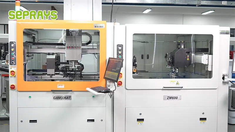
Looking for proven depaneling solutions? Seprays offers a full range of equipment backed by 30+ years of industry experience. Here are two options worth considering for your production line:
- ZM30-D Multi-Tool Multi-Group PCB Depaneling Machine — One-time full LED board cutting — daily output exceeding 100,000 pieces with custom configurations
- GAM310A Offline Automatic Board Separator — Compact single workbench with CCD visual correction — high precision in a small footprint
Frequently Asked Questions
Q1: What cutting tolerance should we specify in the technical data sheet for high-density PCBs with 0201 components to prevent component damage during depaneling?
A1: For 0201 high-density assemblies, the cutting tolerance must be specified at ±0.05mm or tighter, with spindle RPM in the 30,000–40,000 range and monitored cutting stress under 300 με to avoid component cracking. The data sheet should also explicitly state repeat positioning accuracy and anti-vibration performance metrics.
Q2: Our production target is 500k boards per month — which throughput parameters in the depaneler specification should we validate before purchase?
A2: Calculate required throughput at ~1,200–1,500 boards/hour (based on 22 working days/month), then verify the vendor’s “boards/hour” rating against actual feed speed (typically 2,000–3,000 mm/s) and auto-load/unload cycle time. The technical data sheet must also specify ramp-up time and duty cycle to confirm the machine sustains rated throughput over an 8-hour shift.
Q3: The data sheet lists “cutting stress ≤ 500 με” — how does this relate to IPC-9701 compliance and what validation test should we request from the supplier?
A3: IPC-9701 defines the strain limits for post-separation PCB reliability; a spec of ≤ 500 με aligns with Class 2/3 acceptance criteria. Require the supplier to provide strain-gauge test reports measured under actual cutting conditions, confirming peak stress does not exceed the data-sheet value by more than 10%, and request on-site validation using your own board stack-up as part of the FAT (Factory Acceptance Test).
About Seprays
About Seprays Precision Machinery
Founded in 1993, Seprays has over 30 years of expertise in PCB depaneling solutions. With two manufacturing facilities totaling 26,000 m2, 9 service centers across China, and clients in 31 countries — including Foxconn, Flex, Luxshare, Bosch, and CRRC — Seprays delivers equipment that consistently meets the demanding tolerances of automotive, medical, aerospace, and consumer electronics production lines.
Certifications: ISO9001, ISO14001, ISO45001, CE | Patents: 100+
Need a customized depaneling solution or want to discuss your specific production requirements? Our technical team is ready to help.
Contact: jimmy@seprays.com