
Precision Requirements in Server Motherboard Depaneling
A standard enterprise server motherboard panel array typically spans 460mm x 610mm and carries a material cost exceeding USD 800 per panel before component placement. When that same panel has been fully populated with BGAs, high-density connectors, and multi-layer signal routing, the value climbs well past USD 3,500. At this price point, a single depaneling-induced fracture on a DDR5 DIMM trace or a PCIe Gen5 differential pair translates directly into a scrapped board and a measurable yield loss. This economic reality is why server motherboard lines demand routing-based depaneling systems capable of maintaining cutting-path accuracy within plus or minus 0.05mm over the full travel envelope, and why the depaneling station is often the single most tightly toleranced mechanical operation on the entire SMT line.
Routing-Based Depaneling: Spindle and Tool Selection
Routing remains the dominant depaneling method for server motherboards because it produces clean, burr-free edges without introducing significant mechanical stress into the board laminate. High-frequency spindles operating at 40,000 to 80,000 RPM are standard, with collet runout held below 0.005mm to prevent lateral tool deflection during cuts through FR-4 and high-Tg epoxy resin systems. Tool diameter selection follows a straightforward but critical rule: the bit diameter must not exceed 50 percent of the narrowest web width between the board edge and the nearest component pad. For server boards with edge-mounted SMBus connectors or front-panel header clusters spaced at 2.54mm pitch, this typically means 1.0mm to 1.5mm diameter two-flute carbide bits with a 0.2mm tip radius. Feed rates for 1.6mm to 2.4mm thick server-grade PCBs generally fall between 20mm/s and 50mm/s, depending on the number of copper layers and whether the laminate includes high-speed material inserts such as low-Dk halogen-free composites. Exceeding the recommended feed rate for a given laminate stack-up causes delamination at the cut edge, which may not be visible under standard optical inspection but will propagate under thermal cycling per IPC-2221B stress analysis criteria.
Fixture Design and Board Support
Server motherboard arrays frequently contain 2 to 6 individual boards per panel, with tab widths ranging from 3.0mm to 6.0mm. The fixture must provide full underside support within 0.02mm flatness across the entire tool contact zone, because any gap between the board and the fixture surface allows the router bit to induce downward flexure at the moment of breakthrough, creating micro-cracks in inner-layer copper. Vacuum hold-down systems operating at 0.6 to 0.8 bar negative pressure are typical, supplemented by mechanical registration pins that engage tooling holes positioned according to IPC-2221B guidelines at plus or minus 0.025mm true position. For panels incorporating heavy copper layers, which are common in server power-delivery sections carrying 40A to 80A per phase, fixture designers must also account for increased panel stiffness by verifying that the vacuum distribution manifold maintains uniform hold-down force across regions of varying copper thickness. Inconsistent clamping in these zones is a documented root cause of tab tearing and edge chipping on boards with 4oz or 6oz copper inner layers.
Stress Control and Solder Joint Integrity
The primary failure mode during routing-based depaneling is not edge quality but solder joint fatigue induced by vibration transmitted through the PCB substrate. Accelerometer measurements taken at the board surface during routing operations typically show peak vibration amplitudes of 2G to 8G in the 800Hz to 2,000Hz range, depending on spindle speed, feed rate, and fixture rigidity. For ball-grid arrays with 0.4mm pitch and 0.25mm solder ball diameter, repeated exposure to vibration amplitudes above 5G during depaneling has been correlated with early-life crack initiation under thermal shock testing per IPC-9701. Mitigation strategies include reducing feed rate by 15 to 25 percent when cutting within 10mm of large BGA components, increasing fixture mass to dampen resonance frequencies below 500Hz, and using up-cut tool geometry on the final pass to direct cutting forces upward and away from the board surface. Some production lines also implement a two-pass routing strategy, where the first pass cuts to 80 percent depth and the second pass completes the separation, reducing peak vibration amplitude by approximately 40 percent compared to a single-pass cut.
Inline Integration and Throughput Optimization
A server motherboard SMT line typically runs at 3.5 to 5.0 panels per hour at full loading, which means the depaneling station must process a completed panel every 12 to 17 minutes to avoid becoming a bottleneck. Inline routing systems with dual-spindle configurations can achieve cycle times of 8 to 12 minutes per panel for a 4-up array by cutting opposing tabs simultaneously, while offline manual-load systems generally require 15 to 25 minutes per panel including load, align, cut, unload, and visual inspection. Conveyor integration must include board-flip and destack modules downstream of the router, with optical inspection stations verifying edge quality against acceptance criteria defined in IPC-A-610 Class 3 for high-reliability applications. Dust extraction systems rated at 200 to 400 cubic meters per hour with HEPA filtration are mandatory, as the fine FR-4 and copper particulate generated during routing poses both equipment contamination and operator health risks.
Server motherboard depaneling demands a systems-level approach that integrates precise spindle control, rigid fixturing, vibration management, and inline throughput balancing. Cutting-path accuracy within plus or minus 0.05mm, spindle runout below 0.005mm, and vibration amplitudes controlled under 5G near sensitive BGA sites represent the baseline technical thresholds for maintaining first-pass yield above 99.5 percent on high-value server panels. Any weakness in fixture flatness, tool wear monitoring, or dust extraction will eventually manifest as field failures under thermal cycling, making the depaneling station a critical process control point that deserves the same level of engineering rigor applied to solder paste printing and reflow profiling.
Recommended Equipment
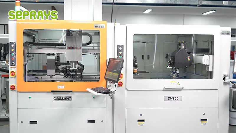
Looking for proven depaneling solutions? Seprays offers a full range of equipment backed by 30+ years of industry experience. Here are two options worth considering for your production line:
- GAM 340AT In-Line Automatic PCB Router Machine — Dual workbench with auto-focus vision camera — maximizes throughput for inline SMT integration
- GAM330AT Fully Automatic PCB Depaneling Machine — Self-feeding operation with automatic sorting — ideal for high-volume automated production lines
Frequently Asked Questions
Q1: What is the primary routing strategy for depaneling high-layer-count server motherboards without damaging blind vias near the panel edges?
A1: Upward routing with carbide end mills (0.8–1.2mm diameter) at 30,000–60,000 RPM is the standard approach. The key is maintaining a minimum 2.0mm routing clearance from all blind via capture pads to prevent crack propagation. Engineers must verify routing direction (clockwise vs counter-clockwise) relative to the board’s stress orientation, as server boards typically have asymmetric layer stackups that create directional weakness.
Q2: How do I balance depaneling throughput with the risk of delamination when processing thermally heavy server board stackups?
A2: Use a two-pass routing strategy: a rough cut at 80% depth with higher feed rates (800–1200mm/min) followed by a finishing pass at reduced feed (300–500mm/min) with chip-load per tooth of 0.03–0.05mm. This approach reduces heat accumulation by 35–40% compared to single-pass aggressive cuts while maintaining 12–18 boards per hour throughput for standard 6-up panels.
Q3: What spindle maintenance interval is required to prevent dust infiltration failures in continuous server motherboard production?
A3: For production volumes exceeding 500 boards per shift, spindle cartridge replacement is required every 1,800–2,200 operating hours, or sooner if bearing noise exceeds 65dB(A). Daily spindle runout checks (maximum 0.008mm TIR) and quarterly bearing oil analysis are mandatory per IPC-A-610 cleanliness standards, since server board flux residue accelerates bearing degradation.
About Seprays
About Seprays Precision Machinery
Founded in 1993, Seprays has over 30 years of expertise in PCB depaneling solutions. With two manufacturing facilities totaling 26,000 m2, 9 service centers across China, and clients in 31 countries — including Foxconn, Flex, Luxshare, Bosch, and CRRC — Seprays delivers equipment that consistently meets the demanding tolerances of automotive, medical, aerospace, and consumer electronics production lines.
Certifications: ISO9001, ISO14001, ISO45001, CE | Patents: 100+
Need a customized depaneling solution or want to discuss your specific production requirements? Our technical team is ready to help.
Contact: jimmy@seprays.com


