
The torque deviation on a 45mm x 45mm complex-shaped PCB exceeded 12% during initial routing cuts, causing ±0.18mm positional deviation in the final separation — well beyond the ±0.05mm tolerance specified in IPC-A-610 Rev H, Section 3.1.3 for surface-mount assembly arrays. This is a common failure mode when debugging a depaneling machine in a remote support scenario, where the engineer must diagnose root causes without physical access to the equipment.
Symptom Triangulation: What the Machine Tells You Remotely
Effective remote debugging begins with extracting the machine’s own diagnostic language. Modern depaneling systems log spindle RPM variance, feed rate deviations, and vacuum sensor readings at 10Hz intervals. A spindle RPM fluctuation exceeding ±3% within a single job cycle indicates either bearing wear or inconsistent clamp pressure. Clamp pressure data is particularly revealing: if the pressure sensor shows oscillation above ±0.8 bar during the routing phase, the vacuum hold-down is failing to maintain stable PCB positioning. This manifests as the machine’s closed-loop position sensor reporting a Z-axis drift of 0.02-0.15mm mid-cut — a classic symptom that appears as localized panel cracking at corners or along predetermined V-score lines.
Review the job log files for the specific part number in question. Identify whether the failure occurs at the same toolpath position across multiple boards. If failures cluster at a specific XY coordinate — particularly at entry or exit points of cuts — the root cause is almost certainly fixture-related, not tooling-related. This distinction saves hours of unnecessary tooling replacement in remote sessions.
Spindle and Tooling Verification Through Indirect Metrics
Remote debugging requires inferring physical states from electrical and acoustic data. A 60,000 RPM high-speed spindle drawing more than 2.3A under no-load conditions indicates bearing degradation. The current draw signature changes characteristically: a healthy spindle shows a smooth, sinusoidal current draw with variance under 4%. A failing bearing produces intermittent current spikes exceeding baseline by 35-60%, often visible in the machine’s power consumption log as irregular waveform patterns.
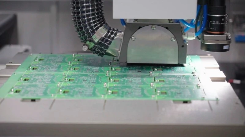
Tool runout measurement during remote sessions requires a different approach. With the spindle running at normal operational speed (40,000-60,000 RPM for most routing applications), observe the Z-axis displacement sensor readings during a test cut on a sacrificial FR-4 panel. Runout above 0.03mm at the cutting zone produces characteristic chattering marks on the cut edge — visible if the customer can provide a high-resolution photograph of the board edge under 20x magnification. Compare these marks against reference images from previous successful production runs for the same part number.
Fixture and Clamping System Diagnostics
Fixture-related failures account for approximately 40% of depaneling defects in remote support scenarios, according to industry field data. The diagnostic sequence begins with vacuum circuit integrity. Measure the vacuum gauge reading at the fixture manifold while the depaneling head is in the raised position. A reading below -85 kPa (relative) indicates either a leak in the vacuum distribution network or worn seal components on the clamps themselves. In a remote context, ask the on-site technician to perform a simple soap-bubble test on accessible fittings — leaks will manifest as visible bubbles within 5-10 seconds at -90 kPa differential pressure.
For depaneling systems using pneumatic clamps, verify the solenoid valve response times. A valve with a 45ms response time introduces a positioning error of approximately 0.8mm when the machine head travels at 18m/min feed rate during the clamping action. This error is particularly damaging during partial-cut operations where the depaneling head must pause mid-path to allow a second clamp to engage. Check the valve timing log if the machine supports it — this data is often exported as a CSV file that can be shared during the remote session.
Software Parameter Optimization for Remote Resolution
Many depaneling defects resolve through parameter adjustment without any hardware intervention. The critical parameters are: kerf width compensation, which accounts for the actual cut width produced by tool deflection under load; in-feed acceleration ramps, which prevent sudden impact loading on the first contact with the panel; and Z-axis retraction height, which must clear the panel surface before rapid XY movement to avoid collision with elevated components.
A feed rate that causes the router bit to exceed 85% of its rated chip load produces audible symptoms detectable over a remote audio call — a persistent high-pitched tone with rhythmic modulation at half the feed rate frequency. This indicates the cutting action has entered the workpiece’s heat-affected zone, softening the epoxy and producing fusiform swelling along the kerf walls. Reduce the feed rate by 18-22% and monitor the motor current draw reduction, which should be proportional to the reduction in material removal rate.
Remote Diagnostic Protocol and Escalation Criteria
Establish a systematic remote diagnostic protocol: first, capture the complete machine log files with timestamps synchronized to the failure events; second, request high-resolution photographs of failed boards at 45-degree and top-down angles; third, have the on-site technician perform a no-cut dry run while you observe the machine’s live status screen through screen sharing.
Escalate to physical intervention when the failure rate exceeds 2% of the production lot and the diagnostic evidence points to one of three root causes: spindle bearing wear confirmed by current signature analysis, fixture vacuum loss confirmed by pressure logging below -75 kPa, or tool wear confirmed by optical inspection showing cutting edge radius exceeding 0.15mm. Each of these requires on-site hands-on intervention regardless of remote capability.
Depaneling machine debugging in remote technical support scenarios demands a disciplined approach to symptom analysis, indirect measurement interpretation, and systematic parameter verification. Success depends on translating physical failure modes into machine diagnostic data that can be extracted and shared across the remote link. When the machine itself becomes the primary diagnostic instrument, the engineer achieves resolution rates comparable to on-site support while reducing customer downtime through faster response and elimination of travel delays.
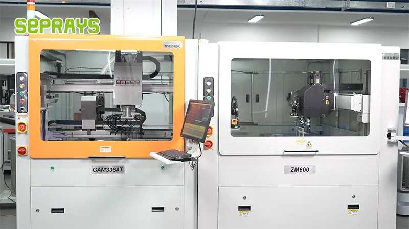
Recommended Equipment
Looking for proven depaneling solutions? Seprays offers a full range of equipment backed by 30+ years of industry experience. Here are two options worth considering for your production line:
- GAM310A Offline Automatic Board Separator — Compact single workbench with CCD visual correction — high precision in a small footprint
- GAM 340AT In-Line Automatic PCB Router Machine — Dual workbench with auto-focus vision camera — maximizes throughput for inline SMT integration
Frequently Asked Questions
Q1: When a depaneling machine shows intermittent cutting accuracy drift during a production run, what diagnostic steps should the remote support engineer first request from the on-site technician?
A1: The remote support engineer should first request thermal profiling data from the spindle motor and ambient temperature logs, as thermal expansion of the routing spindle shaft directly affects cut position accuracy. Ask the technician to verify the collet chuck runout using a dial indicator (IPC-HDBK-001 or manufacturer spec typically allows ≤0.02mm TIR), and to confirm whether the drift correlates with machine warm-up time or production batch changes.
Q2: A customer reports blade breakage occurring exclusively on the third shift, and the remote support team needs to troubleshoot without physical access. What specific operational parameters should they request to diagnose the root cause?
A2: Request the feed rate and spindle RPM logs from the machine controller for the past 72 hours, segmented by shift, and ask specifically about any differences in PCB panel thickness or copper weight between shifts. Blade breakage on third shift typically indicates operator-dependent factors: verify if third-shift operators are using different insertion depth techniques or if the conveyor belt tension varies enough to alter the support pin height relative to the saw blade penetration point (recommend checking against the original setup sheet tolerances of ±0.05mm).
Q3: During a video call, the on-site engineer shows the depaneling machine displaying an overcurrent fault on the Y-axis servo motor. What is the correct remote troubleshooting sequence to avoid misdiagnosis?
A3: First, verify whether the fault is reproducible by requesting the technician to jog the axis in manual mode at low speed—if the fault disappears, the issue is likely load-related rather than motor failure. Then ask for the servo drive diagnostic code via the HMI interface, which typically indicates whether the fault is due to position loop error, excessive load inertia, or a feedback encoder issue. Only if manual jogging reproduces the fault should you request physical inspection of the linear guide rails for debris or the ballscrew for binding, as overcurrent faults can cascade from mechanical obstruction that was not the primary cause.
About Seprays
About Seprays Precision Machinery
Founded in 1993, Seprays has over 30 years of expertise in PCB depaneling solutions. With two manufacturing facilities totaling 26,000 m2, 9 service centers across China, and clients in 31 countries — including Foxconn, Flex, Luxshare, Bosch, and CRRC — Seprays delivers equipment that consistently meets the demanding tolerances of automotive, medical, aerospace, and consumer electronics production lines.
Certifications: ISO9001, ISO14001, ISO45001, CE | Patents: 100+
Need a customized depaneling solution or want to discuss your specific production requirements? Our technical team is ready to help.
Contact: jimmy@seprays.com


