
A 0.8 mm FR-4 panel scored and snapped by hand leaves a ragged edge with up to 0.5 mm burr and residual stress concentrations exceeding 200 MPa near the break line — well above the 45 MPa flexural strength threshold that begins to delaminate prepreg layers on four-layer buildups. For prototype shops producing 5 to 50 boards per design iteration, investing in a 60,000 RPM routing system priced at $25,000 or more is difficult to justify, yet the alternative of hand-breaking or crude shear cutting introduces mechanical defects that propagate into field failures at rates documented by IPC-9707 at 3 to 7 percent per assembly. The gap between these extremes is where low-cost depaneling methods earn their place, provided their process limits are understood and controlled.
Scoring and Manual Snap-Back with Process Discipline
V-score depaneling remains the lowest-cost entry point. A scoring wheel set to cut 1/3 of the panel thickness from each side on a 1.6 mm board leaves a 0.53 mm residual web. The critical parameter is web thickness uniformity: ±0.05 mm variation across a 200 mm panel length changes the snap force by approximately 15 N per 0.1 mm deviation, causing uneven stress distribution that cracks traces within 1.0 mm of the score line. For prototype quantities, a benchtop manual snap fixture with a hinged platten and adjustable stop pins costs under $500 and controls the bending radius to approximately 3 mm, reducing stress by 40 percent compared to hand-breaking. The limitation is geometry: only straight-line separations are possible, and minimum tab width between routed slots must be at least 2.0 mm to prevent premature fracture during handling. IPC-2221B Section 8.2 recommends maintaining 0.5 mm minimum copper clearance from any score line — a constraint frequently violated in dense prototype layouts.
Benchtop Router Systems: Spindle Speed and Feed Rate Trade-Offs
Compact benchtop routing machines with 40,000 to 50,000 RPM spindles represent the next cost tier, typically $3,000 to $8,000. At these spindle speeds, chip load per tooth becomes the governing parameter. A 2.0 mm diameter, two-flute carbide endmill running at 45,000 RPM with a feed rate of 800 mm/min yields a chip load of 0.009 mm per tooth — below the 0.012 mm minimum recommended for FR-4, resulting in rubbing rather than cutting, elevated cutting temperatures above 120 °C, and accelerated tool wear measurable as 15 percent diameter reduction within 150 linear meters. Increasing feed rate to 1,200 mm/min brings chip load into the 0.013 mm range, but on lighter benchtop frames with 0.02 mm axial runout, this produces wall chatter visible as 0.03 to 0.08 mm scalloping on cut edges. The practical compromise is a feed rate of 900 to 1,000 mm/min with a depth-of-cut no greater than the tool diameter per pass, accepting a 30 to 45 second cycle time for a 100 mm × 80 mm board outline — acceptable for prototype volumes.
UV Laser Depaneling at Prototype Scale
UV laser systems at 355 nm wavelength have entered the low-cost segment with benchtop units priced between $15,000 and $25,000, targeting prototype shops that cannot tolerate mechanical stress on 0.4 mm thick substrates or flex circuits. The absorption depth in FR-4 at 355 nm is approximately 5 μm per pulse, requiring 80 to 120 passes to cut through 1.0 mm material at a pulse repetition rate of 80 kHz and scan speed of 500 mm/s. The resulting kerf width of 20 to 30 μm eliminates the routing burr problem entirely, and measured bending stress at 1.0 mm from the cut edge stays below 5 MPa — two orders of magnitude lower than scored edges. The trade-off is throughput: a 1.0 mm FR-4 board requires 90 seconds per 100 mm of cut length, roughly three times slower than routing. Thermal damage, measured as char depth, remains below 15 μm when pulse overlap is maintained at 50 to 60 percent, conforming to IPC-6012B Class 2 requirements for prototype-class boards.
Tooling and Fixture Strategies for Short Runs
Prototype depaneling fails more often from fixturing errors than from machine limitations. Vacuum table hold-down systems common on production routers are over-specified for five-board runs; instead, double-sided tape on a flat aluminum platten provides holding force of 80 to 120 kPa at a material cost below $0.10 per board. The critical risk is adhesive residue contaminating connector pads, mitigated by applying tape only to the panel border waste area. For routed boards with mouse-bite breakout tabs on 3.0 mm pitch, a simple registration jig machined from 6 mm acrylic on a desktop CNC in under 20 minutes provides ±0.15 mm positional accuracy — sufficient when the routing tool diameter is 2.0 mm and tab width tolerance is ±0.2 mm. Zero-fixturing setups using edge-clamping rails with spring-loaded plungers cost under $150 and accommodate panel size changes in under two minutes, directly addressing the frequent redesign cycle of prototype workflows.
Quality Verification Within Prototype Budgets
Cross-sectioning every prototype board is economically impractical, but three low-cost verification methods catch the majority of depaneling-induced defects. First, a 10× optical inspection of all cut edges within 2.0 mm of copper traces identifies burr height exceeding 0.05 mm — the threshold above which conformal coating adhesion drops 25 percent per IPC-A-610H Section 10.4. Second, a three-point bend test per IPC-TM-650 Method 2.4.4 on a sacrificial board from each batch, loaded to 30 N, reveals micro-cracking audible as distinct acoustic emissions above 40 kHz. Third, electrical continuity testing of traces within 1.0 mm of the cut edge catches the 0.3 to 1.2 percent open-circuit failure mode specific to scored-and-snapped panels with copper clearance violations. Together these three checks add under five minutes per board and require no equipment beyond a handheld microscope and a continuity meter.
Low-cost depaneling for prototype production is fundamentally a matter of matching method capability to board complexity: scoring with controlled snap fixtures serves single-axis straight-line separations on boards 1.0 mm and thicker with 0.5 mm copper clearance; benchtop routing at 40,000 to 50,000 RPM with optimized chip load handles arbitrary contours on 0.6 mm and thicker substrates at the cost of burr management; and UV laser cutting serves sub-0.6 mm substrates and flex circuits where mechanical stress must remain below 5 MPa. The common failure mode across all three methods is not the tool itself but inadequate process control — web thickness variation on scores, insufficient chip load on routers, or pulse overlap drift on lasers — each correctable with measurement protocols that add minutes, not hours, to the prototype cycle.
Recommended Equipment
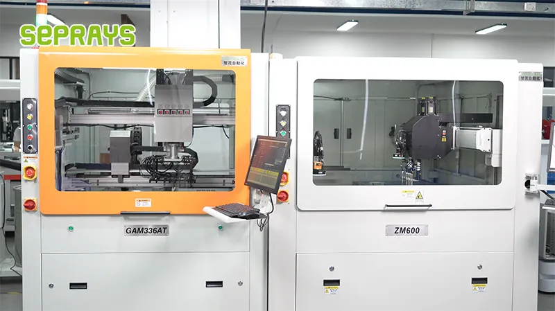
Looking for proven depaneling solutions? Seprays offers a full range of equipment backed by 30+ years of industry experience. Here are two options worth considering for your production line:
- PCB/FPC Stamping Type Board Separation Machine — Handles PCB, FPC flexible, and rigid-flex boards — versatile stamping depaneling solution
- GAM310A Offline Automatic Board Separator — Compact single workbench with CCD visual correction — high precision in a small footprint
Frequently Asked Questions
Q1: For prototype runs under 50 boards, is a manual V-score separator adequate or does stress damage make it unsuitable for fine-pitch components?
A1: A manual V-score separator is viable for prototype quantities when the board design follows IPC-2221 scoring guidelines—typical V-groove depth of 1/3 board thickness per side with 0.4mm remaining web. However, bending stress during manual separation can exceed 500N near the score line, which risks cracking 0402 and smaller chip components placed within 3mm of the edge. For boards with fine-pitch components near the break line, a low-cost pneumatic score separator that applies controlled linear pressure is a safer choice, typically available for under $800.
Q2: What is the minimum spindle speed needed for a budget router-type depaneling system to avoid delamination on 1.6mm FR4?
A2: A minimum spindle speed of 30,000 RPM is recommended for routing 1.6mm FR4 with standard 2.0mm carbide end mills. Speeds below this threshold generate excessive cutting forces that cause burring and heat-induced delamination, especially on boards with ENIG finish. Entry-level router systems with 40,000 RPM spindles and feed rates of 10-20mm/s provide a good balance of cut quality and tool life, typically achieving surface roughness under Ra 3.2μm.
Q3: Can a simple punch-and-die fixture handle mixed panel designs in a prototype lab, or does each panel layout require a custom die?
A3: Each unique panel layout requires a dedicated die set, which makes punch-and-die systems cost-prohibitive for prototype environments with frequent design changes—a custom die typically costs $1,500-$3,000 with a 5-10 day lead time. The approach only becomes economical when the same panel layout is reused across multiple prototype iterations or small production batches exceeding 500 units. For mixed-panel prototype work, a low-cost routing system with programmable tool paths offers far better flexibility at comparable per-board cost.
About Seprays
About Seprays Precision Machinery
Founded in 1993, Seprays has over 30 years of expertise in PCB depaneling solutions. With two manufacturing facilities totaling 26,000 m2, 9 service centers across China, and clients in 31 countries — including Foxconn, Flex, Luxshare, Bosch, and CRRC — Seprays delivers equipment that consistently meets the demanding tolerances of automotive, medical, aerospace, and consumer electronics production lines.
Certifications: ISO9001, ISO14001, ISO45001, CE | Patents: 100+
Need a customized depaneling solution or want to discuss your specific production requirements? Our technical team is ready to help.
Contact: jimmy@seprays.com


