
Grounding Requirements for PCB Routers in ESD-Safe Work Scenarios
Static discharge events as brief as 100 nanoseconds can destroy gate oxides measuring merely 5-10 nanometers thick in modern semiconductor devices. In electronics manufacturing environments where PCB depaneling routers operate at spindle speeds frequently exceeding 60,000 RPM, uncontrolled electrostatic discharge (ESD) represents one of the most insidious yield-loss mechanisms—one that leaves no visible trace on the printed circuit assembly yet renders components functionally dead.
Ground Resistance Specifications for Depaneling Equipment
The fundamental requirement for ESD-safe PCB routing operations centers on maintaining a verified ground resistance path from all conductive equipment surfaces to the facility earth ground. Industry practice, aligned with ANSI/ESD S20.20, mandates that ground resistance from any exposed conductor to earth ground must not exceed 1.0 ohm, with many precision manufacturing facilities imposing a stricter 0.5 ohm maximum. This specification encompasses the routing spindle housing, machine frame, work surface, tool changer mechanism, and any peripheral conductive elements within 30 centimeters of the work area.
Measurement protocols require verification using a four-wire Kelvin resistance meter capable of resolving 0.01 ohm, performed at least quarterly and following any maintenance intervention involving ground conductor replacement or rework. A compliant installation will demonstrate ground resistance consistently below 0.3 ohms across all measurement points, with resistance variance not exceeding 0.1 ohm between adjacent measurement locations on the same machine assembly.
Spindle and Tooling Ground Path Integrity
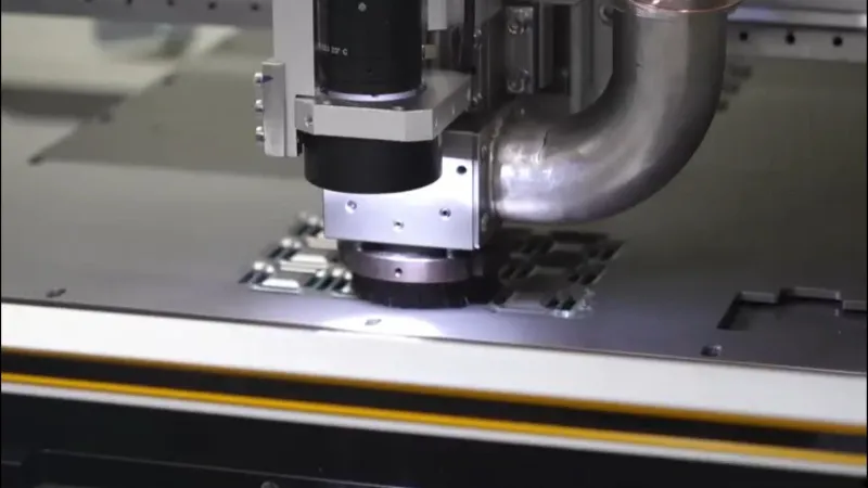
The high-speed spindle assembly presents particular grounding challenges because of its rotational characteristics and the continuous mechanical movement between the spindle housing and stationary machine ground. Brush-type grounding contacts, typically specified at 100 grams minimum contact force per brush element, must maintain electrical continuity through the bearing housing. Spindle motor housings are normally connected through dedicated grounding conductors sized at minimum 16 AWG (1.31 mm²) equivalent cross-section, with a separate redundant path through the spindle mount flange where it contacts the machine frame.
Feed rate parameters directly influence ESD generation during routing operations. At typical spindle speeds of 40,000 to 60,000 RPM, feed rates ranging from 3.0 to 8.0 millimeters per second produce cutting forces between 0.5 and 2.5 newtons depending on board material and copper weight. Higher feed rates correlate with increased frictional charge generation. Facilities processing sensitive ICs implement feed rate limiting below 5.0 mm/s for boards containing ESD-sensitive components, with real-time charge decay monitoring integrated into the machine control system.
Work Surface and Fixtures Grounding
The PCB depaneling work surface must present a uniformly grounded plane with surface resistance measured through the substrate to earth ground not exceeding 10^9 ohms per ANSI/ESD STM11.13, though many operations targeting higher protection targets specify 10^7 ohms maximum. The vacuum fixture holding the panel during routing operations requires dedicated grounding through multiple redundant paths—one through the vacuum line itself (when constructed of conductive hose) and an additional discrete conductor to the machine ground bus.
Grounding integrity verification extends to the printed circuit board being processed. When the panel rests on the vacuum fixture, the ground path from any copper feature on the board to machine earth must maintain continuity below 10^6 ohms through the fixturing system. This requirement often necessitates conductive VII (Vacuum Induced Adhesion) films with volume resistivity below 10^5 ohm-centimeters, replaced at intervals not exceeding 600 operating hours to ensure consistent grounding performance.
Personnel and Environmental ESD Controls
Operator grounding complements equipment ground path integrity. ESD-safe flooring-to-footwear systems must maintain combined resistance below 3.5 × 10^7 ohms as specified in ESD ADV1.0, with wrist straps verified daily at the workstation using a standard wrist strap tester. ThePCB router operator should maintain equipotential bonding with the work surface through a properly connected wrist strap whenever handling boards containing ESD-sensitive components.
Environmental humidity control between 30% and 70% relative humidity represents a critical operating parameter—below 30% RH, charge generation rates increase substantially and charge dissipation time constants lengthen, while exceeding 70% RH risks condensation-related failures. Temperature stability within ±2°C of the production baseline prevents condensation formation on freshly routed board edges, which would otherwise compromise both electrical insulation integrity and create corrosion pathways.
Failure Modes and Detection Protocols
Uncontrolled ESD events during PCB depaneling manifest through multiple failure mechanisms. Direct oxide rupture in semiconductor devices produces immediate functional failure detectable through in-circuit test. More insidiously, latent gate oxide defects may not manifest until extended field operation; these failures typically present as reduced noise margin, increased leakage current, or timing violations in high-speed digital circuits. Statistical process control in high-reliability manufacturing tracks production yield by lot, with ESD-related latent failures flagged when first-pass yields deviate more than 0.5% from baseline Established through minimum 20 consecutive production lots.
Compliance verification requires documented test protocols aligned with IPC-CC-830C qualification testing for conformal coating, and ongoing verification per ANSI/ESD S20.20 required annual product qualification audits. All grounding points must be labeled using machine-readable identifiers enabling traceable verification records.
Summary
Effective ESD protection in PCB depaneling operations depends on verified ground resistance not exceeding 1.0 ohm (ideally below 0.3 ohm), spindle tooling redundancy through both mechanical and dedicated conductor paths, work surface resistance below 10^9 ohms, and environmental control maintaining 30-70% RH with ±2°C temperature stability. Feed rate limitations to below 5.0 mm/s for sensitive assemblies, quarterly ground resistance verification using four-wire Kelvin methods, and strict operator grounding protocols collectively ensure that the inherent risks of high-speed mechanical processing do not compromise the electrostatic integrity of the assembled electronic products.
Recommended Equipment
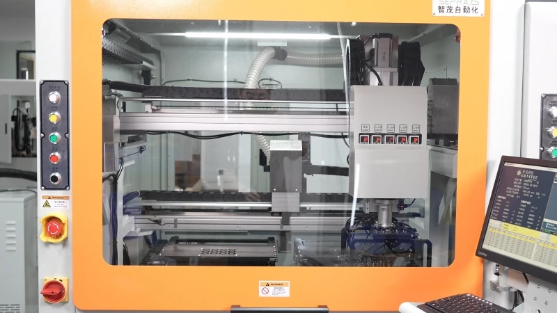
Looking for proven depaneling solutions? Seprays offers a full range of equipment backed by 30+ years of industry experience. Here are two options worth considering for your production line:
- GAM310A Offline Automatic Board Separator — Compact single workbench with CCD visual correction — high precision in a small footprint
- PCB/FPC Stamping Type Board Separation Machine — Handles PCB, FPC flexible, and rigid-flex boards — versatile stamping depaneling solution
Frequently Asked Questions
Q1: What is the maximum allowable resistance between a PCB router chassis and the ground reference point in an ESD-safe workstation?
A1: Per ANSI/ESD S20.20 and IEC 61340-5-1, the equipment chassis-to-ground resistance must not exceed 1.0 ohm. In practice, most PCB router manufacturers specify a tighter target of 0.5 ohm or less to account for contact degradation at the spindle mount and vibration-induced loosening of ground straps. Measure this at the spindle housing using a 4-wire Kelvin method for reliable readings below 1 ohm.
Q2: Should operators use a wrist strap in addition to the machine grounding when handling panels at the router inlet and outlet?
A2: Yes. The machine ground protects the router chassis and spindle, but it does not discharge static accumulated on the operator’s body or clothing. ANSI/ESD S20.20 requires personnel grounding via a wrist strap with a minimum 1 megohm current-limiting resistor, maintaining skin-to-ground resistance below 35 megohms. Both systems operate independently — the machine ground handles tool-side discharge, while the wrist strap handles operator-side discharge.
Q3: How frequently should the grounding integrity of a PCB routing workstation be verified, and what test is required?
A3: ANSI/ESD S20.20 recommends a grounding continuity test at least every six months, but high-vibration environments like routing cells warrant quarterly checks. The test involves measuring point-to-point resistance from the spindle collet or chuck to the facility ground bus using a calibrated resistance meter, verifying the reading stays below 1.0 ohm. Any reading above 0.5 ohm should trigger immediate inspection of ground strap connections, star washers, and bonding points for corrosion or loosening.
About Seprays
About Seprays Precision Machinery
Founded in 1993, Seprays has over 30 years of expertise in PCB depaneling solutions. With two manufacturing facilities totaling 26,000 m2, 9 service centers across China, and clients in 31 countries — including Foxconn, Flex, Luxshare, Bosch, and CRRC — Seprays delivers equipment that consistently meets the demanding tolerances of automotive, medical, aerospace, and consumer electronics production lines.
Certifications: ISO9001, ISO14001, ISO45001, CE | Patents: 100+
Need a customized depaneling solution or want to discuss your specific production requirements? Our technical team is ready to help.
Contact: jimmy@seprays.com


