
High-Reliability Requirements for PCB Depaneling in Industrial Power Modules
In industrial power module manufacturing, PCB depaneling is not merely a post-assembly cutting step. Multi-layer substrates with thicknesses reaching 3.2 mm and copper weights up to 6 oz per square foot routinely undergo separation stresses during this process. If those stresses exceed the substrate’s interlaminar bond strength, delamination initiates at the panel edges — a failure mode that may not manifest until field operation, when thermal cycling amplifies existing micro-cracks into catastrophic module failure. Controlling that stress pathway is the fundamental engineering challenge of depaneling high-reliability power electronics.
Stress Dynamics at the Panel Edge
When a routing bit or shearing blade separates a panelized array, the cutting zone experiences a transient spike in localized stress. For FR-4 and polyimide-based power module substrates, the maximum allowable shear stress at the point of separation must remain below 15 N/mm² to prevent interlaminar micro-cracking. High-frequency rotary routing — operating at spindle speeds of 60,000 to 80,000 RPM — distributes that stress over a narrower kerf width (typically 0.3 to 0.5 mm), reducing the peak force transmitted into adjacent component areas compared to low-speed blade shearing, which can generate stress concentrations exceeding 40 N/mm² at the immediate cut line. For boards with high-voltage isolation requirements (creepage distances of 2.5 mm and above per IEC 60664), any edge chipping wider than 0.15 mm creates a surface defect that compromises the conformal coating adhesion and, consequently, the partial discharge resistance of the module.
Tolerance Control for High-Density Arrays
Industrial power modules frequently incorporate IGBT dies, SiC MOSFETs, and bus bars in the same assembly, with lead spacings as tight as 1.0 mm pitch. Panelized arrays with 2×4 or 3×4 board configurations must be separated with positional accuracy of ±0.05 mm at each cut transition. A positional error exceeding ±0.1 mm at the junction between adjacent modules introduces mechanical misalignment in the press-fit connectors or bolted bus bar joints, creating localized current crowding with current density hotspots exceeding 500 A/cm² in those offset regions. Computer-numerically-controlled depaneling systems with linear encoder feedback loops achieving 0.01 mm resolution are therefore specified for power module production lines, rather than manual or pneumatically-actuated standalone units which typically achieve only ±0.2 mm positional repeatability under dynamic cutting loads.
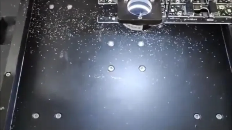
Thermal Management Considerations During Routing
The friction heat generated during high-speed routing of a 3.2 mm thick substrate can elevate the cutting zone temperature by 40°C to 80°C above ambient within 2 to 3 seconds of continuous engagement. For substrates with high glass transition temperatures (Tg = 170°C or above), this transient thermal spike remains below the Tg threshold. However, prolonged engagement at feed rates below 15 mm/second without active debris extraction causes thermal accumulation that softens the resin matrix, leading to slit-line taper and dimensional non-conformance. Optimal feed rates for 3.2 mm thick power module substrates range from 20 to 35 mm/second using carbide or diamond-coated routing bits with a helix angle of 30° to 38°, which simultaneously manages chip evacuation and heat dissipation. The recommended bit diameter is 2.0 to 3.175 mm with a clearance angle of 6° to 10°, producing a clean kerf without resin smear on the cut edge — a condition verified under 40× magnification per IPC-A-600H acceptability criteria for conductor and base material integrity.

Depaneling Method Selection: Routing vs. Laser
Laser depaneling eliminates mechanical contact entirely, eliminating chip formation and the associated risk of conductive debris lodging between high-voltage traces. For boards where the minimum distance between the cut line and the nearest SMT component is less than 0.8 mm — which is increasingly common in miniaturized SiC power modules — laser systems with a kerf width below 0.05 mm provide a decisive advantage. However, the heat-affected zone (HAZ) from CO₂ or UV laser ablation must remain below 0.1 mm to avoid copper layer discoloration and surface oxide formation that degrades solderability. For most industrial power module assemblies where component clearance exceeds 1.5 mm, high-speed mechanical routing with active dust extraction at a negative pressure of 150 to 250 mbar remains the more cost-effective and technically proven solution, provided the spindle runout is controlled below 0.01 mm total indicated runout (TIR) as specified in ISO 1940-1 for precision balancing.
Quality Assurance and IPC Compliance
Every depaneled board must be evaluated against IPC-2223C (sectional design standard for flexible/rigid printed boards) for edge quality and IPC-A-600H for surface defect acceptance. In high-reliability power module production, 100% automated optical inspection (AOI) of cut edges is mandatory, targeting crack detection, burring, and delamination voids within 0.1 mm of the cut line. Destructive cross-section analysis at a sampling rate of one board per 500 panels, per IPC-2221A generic standard for printed board design, verifies the absence of interlaminar separation and confirms that the routing parameters are producing a metallurgically intact edge profile. When production data shows a cut-edge defect rate exceeding 0.5%, the spindle speed, feed rate, and bit condition must be recalibrated before resuming full-volume runs, since degraded cutting edges directly correlate with increased stress concentration and accelerated fatigue failure under thermal cycling conditions.
The separation of individual power modules from a production panel is a precision stress-controlled process where spindle speed, feed rate, positional accuracy, thermal management, and edge quality inspection must be optimized as an integrated system. For high-reliability industrial power modules operating at elevated temperatures and high current densities, marginal depaneling practices are not tolerable — the cost of a field failure in an industrial power conversion system vastly exceeds any savings realized by reducing inspection or tolerancing rigor during the board-separation step.
Recommended Equipment
Looking for proven depaneling solutions? Seprays offers a full range of equipment backed by 30+ years of industry experience. Here are two options worth considering for your production line:
- GAM330AT Fully Automatic PCB Depaneling Machine — Self-feeding operation with automatic sorting — ideal for high-volume automated production lines
- ZM30-D Multi-Tool Multi-Group PCB Depaneling Machine — One-time full LED board cutting — daily output exceeding 100,000 pieces with custom configurations
Frequently Asked Questions
Q1: What is the main challenge discussed in this article?
A1: This article explores practical considerations for PCB depaneling operations in manufacturing environments, covering key factors that affect quality, efficiency, and cost.
Q2: How does this relate to production quality?
A2: Improper depaneling can damage components, introduce stress, and compromise board integrity. Choosing the right method directly impacts your final product quality and yield rate.
Q3: What depaneling methods are available?
A3: Common methods include router depaneling (best for complex shapes), V-cut depaneling (cost-effective for high volume), and laser depaneling (ultra-precise, minimal stress).
About Seprays
About Seprays Precision Machinery
Founded in 1993, Seprays has over 30 years of expertise in PCB depaneling solutions. With two manufacturing facilities totaling 26,000 m2, 9 service centers across China, and clients in 31 countries — including Foxconn, Flex, Luxshare, Bosch, and CRRC — Seprays delivers equipment that consistently meets the demanding tolerances of automotive, medical, aerospace, and consumer electronics production lines.
Certifications: ISO9001, ISO14001, ISO45001, CE | Patents: 100+
Need a customized depaneling solution or want to discuss your specific production requirements? Our technical team is ready to help.
Contact: jimmy@seprays.com


