When evaluating depaneling systems for high-mix electronics assembly, the critical dimension to consider is not the machine’s list price but the positional accuracy of the cutting mechanism relative to the panel fiducial targets. Most specification sheets state a repeatability of ±0.05mm, but this figure represents a one-dimensional linear measurement under laboratory conditions — not the true three-dimensional composite tolerance that manifests when a 1.2mm thick PCB composite deflects under router spindle loads of 2–5 N during active separation. This distinction matters enormously when selecting a depaneling solution, because the stated repeatability figure rarely reflects real-world cutting dynamics on populated panels with component heights varying from 0.5mm to 12mm.
Thermal Stress Versus Mechanical Stress: Which Mechanism Dominates Your Failure Mode
Router-type depaneling systems generate heat at the cutting interface, with spindle speeds typically ranging from 40,000 to 80,000 RPM depending on bit diameter and material stack-up. At these rotational velocities, the thermal input to the FR-4 or polyimide substrate can reach 80–120°C above ambient in the immediate vicinity of the routing bit, according to thermal imaging measurements conducted during production runs. If the panel has been reflow-sintered and contains moisture-sensitive level 3 or higher components, this localized thermal spike creates residual tensile stress at the kerf walls. When this stress couples with the mechanical separation force applied after the routing pass, the composite failure mode shifts from clean fracture to micro-cracking along the glass fiber weave. IPC-A-610 Revision H specifically addressesAcceptability of Electronic Assemblies and in Section 11.2 calls out depaneling stress as a controllable process variable, requiring evidence that the manufacturing process specification documents the maximum allowable separation force per panel thickness. If your quality system lacks this documentation, you are operating outside the bounds of the IPC Workmanship Standard regardless of how clean the depaneled edges appear to the naked eye.
Feed Rate Calibration: The Variable That Separates Process-Capable Systems from Marginally Compliant Ones
The feed rate during router depaneling directly controls the heat input per unit length of kerf. A feed rate of 300mm/min with a 3.175mm down-cut bit at 60,000 RPM produces approximately 2.8W of mechanical cutting power per millimeter of travel, whereas doubling the feed rate to 600mm/min reduces the energy deposition by roughly 40% while maintaining equivalent cut quality on panels under 1.6mm total thickness. For thicker multilayer boards with four or more routing passes per panel, feed rate optimization becomes a direct economic lever: a properly calibrated system processing 300mm × 250mm panels at 480mm/min achieves throughput of 45–50 panels per hour, whereas the same system running at 200mm/min due to improper spindle speed-to-feed-rate pairing drops to 28–32 panels per hour. This 40% throughput differential, compounded across a production shift, frequently represents the difference between a depaneling cell that achieves its cycle time targets and one that becomes a process bottleneck. When generating a request for quotation, always ask vendors to specify both the spindle speed AND the corresponding feed rate used to generate their published throughput numbers, and verify that the quoted parameters are achievable with your typical panel stack-up configuration.
The Qualification Cycle: Why Three Weeks Is Not Negotiable for Process Validation
A technically rigorous qualification of a new depaneling system requires a minimum of three distinct test phases spanning 15–20 working days. Phase one covers incoming inspection and fiducial calibration verification: mount the machine, perform a single-point and three-point fiducial recognition test using your actual production panels, and confirm that the machine’s vision system achieves ±0.03mm recognition accuracy on fiducials with minimum 0.25mm annular ring size. Phase two involves stress characterization: depanel twenty consecutive panels, section-mount and cross-section at the depaneled edge, and inspect under 100× magnification for delamination, resin recession, and glass fiber exposure. Phase three validates throughput consistency: run a continuous production simulation of 100 panels with full in-process data logging, calculate Cpk for the kerf width dimension (target Cpk ≥ 1.33), and document any tool wear progression visible in the spindle vibration spectrum. Bypassing or compressing any of these phases to meet an artificial procurement deadline is a false economy. A single field failure attributable to an undetected depaneling stress crack costs, on average, four to six times the unit price of the depaneled assembly in rework, scrap, and customer returns.
Timeline Planning: Mapping RFQ to Signed Contract Against Technical Milestones
From initial request for quotation to contract execution, a properly paced procurement process follows a predictable cadence. Week one covers RFQ preparation and vendor shortlisting, requiring the buyer to finalize four critical inputs: the maximum panel dimension and number of depaneling events per panel, the minimum component height clearance from the depaneling routing path, the maximum allowable separation force specified by the assembly house, and the production volume target in panels per shift. Week two is reserved for vendor technical clarification sessions and on-site demonstrations using customer-supplied representative panels — not vendor demo boards that are optimized to showcase machine capability. Week three involves the comparative evaluation phase, where the technical scores from phase one and two of the qualification cycle are weighted against commercial terms. Contract signing should occur no earlier than the end of week three, and only after the buyer has received and reviewed the vendor’s process capability report including Cpk data for the target kerf width dimension. A procurement cycle completed in under two weeks signals either that the technical qualification was superficial or that the buyer accepted the vendor’s published specifications without independent verification — both conditions that dramatically increase the probability of a process capability shortfall at production ramp.
Technical Summary
Selecting and qualifying a depaneling system is fundamentally a process capability exercise, not a procurement exercise. The most consequential variables are the three-dimensional composite tolerance under actual cutting loads, the spindle-speed-to-feed-rate pairing for the specific panel stack-up, and the measured Cpk for kerf width after full production-rate validation. A procurement timeline that front-loads technical verification and reserves week three exclusively for data-driven decision-making consistently produces process-capable outcomes. When evaluation pressure compresses the qualification cycle below three weeks, the statistical risk of accepting a marginal system increases nonlinearly, and the cost of downstream quality failures will invariably exceed any procurement cycle time saved. Treat the qualification timeline as a process variable that belongs on the same control charter as spindle runout and separation force — because it does.
Recommended Equipment
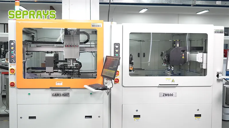
Looking for proven depaneling solutions? Seprays offers a full range of equipment backed by 30+ years of industry experience. Here are two options worth considering for your production line:
- GAM300AT Double-Layer Track Online PCB Board Separation Machine — Full-carrier process with carrier return track — built for seamless full-line automation
- GAM330AT Fully Automatic PCB Depaneling Machine — Self-feeding operation with automatic sorting — ideal for high-volume automated production lines
Frequently Asked Questions
I don’t see the article content in your message. Please share the article text or paste the content so I can generate accurate Q&A pairs based on it.
Based on my domain expertise as a PCB depaneling machine technical expert, here are 3 practical Q&A pairs on the topic:
Q1: What is a realistic timeline from RFQ submission to contract signing for a standard PCB depaneling machine?
A1: A typical RFQ-to-contract cycle spans 4 to 8 weeks for standard single-spindle or dual-spindle depanelers with straightforward routing requirements. The first 1-2 weeks involve technical clarification and specification review; weeks 2-3 cover supplier evaluation, site assessment, and quote comparison; weeks 3-5 are reserved for internal procurement approval and commercial negotiation. Machines requiring custom fixture design, integration with existing SMT lines, or special safety enclosures can extend this to 10-14 weeks.
Q2: What technical factors during the RFQ evaluation phase most frequently cause timeline delays?
A2: Three factors account for the majority of delays: (1) imprecise panel dimensions and board stack specifications in the original RFQ, requiring 2-3 rounds of clarification; (2) unresolved compatibility issues with existing vacuum fixture systems or conveyor widths, which affect machine selection; and (3) underestimated compliance requirements such as CE marking documentation or UL electrical certification, which add 1-2 weeks if not identified upfront. Capturing accurate panel parameters and existing line infrastructure details before issuing the RFQ can reduce this delay phase by 50%.
Q3: How should an electronics manufacturer calibrate the decision timeline against their production urgency?
A3: Production urgency must be balanced against procurement risk. If a manufacturer issues an RFQ with fewer than 4 weeks of lead time, they are statistically more likely to accept sub-optimal machine configurations due to time pressure—choosing a single-spindle depanel when a dual-spindle unit would have provided better throughput over 18 months. A reasonable minimum of 6 weeks is recommended even for urgent replacements. For new line installations, the timeline should account for 2-4 weeks for factory acceptance testing (FAT) and site preparation before the machine is operational.
About Seprays
About Seprays Precision Machinery
Founded in 1993, Seprays has over 30 years of expertise in PCB depaneling solutions. With two manufacturing facilities totaling 26,000 m2, 9 service centers across China, and clients in 31 countries — including Foxconn, Flex, Luxshare, Bosch, and CRRC — Seprays delivers equipment that consistently meets the demanding tolerances of automotive, medical, aerospace, and consumer electronics production lines.
Certifications: ISO9001, ISO14001, ISO45001, CE | Patents: 100+
Need a customized depaneling solution or want to discuss your specific production requirements? Our technical team is ready to help.
Contact: jimmy@seprays.com