When a routing tool spinning at 60,000 RPM
approaches a 1.2mmthick FR4 panel along a pre-scored milling path, the dynamic stress wave generated at the toolworkpiece interface can exceed 180 MPa within the first 0.3 milliseconds of contact. This microsecond-scale event determines whether a depaneled PCB exits the machine with pristine 0.15mm cleanup tabs and zero risk, or arrives at final test with latent interfacial delamination that surfaces weeks later in the field. The engineering decisions made before that tool engages the panel — spindle selection, feed rate programming, bit geometry, and fixture clamping strategy — constitute the core technical discipline of PCB depaneling, a process that accounts for approximately 3-8% of all assembly defects traced back to post-solder handling according to industry failure analysis surveys.
Vibration Modes and Dynamic Precision Requirements
Modern PCB depaneling operates under tolerance regimes that are fundamentally constrained by structural dynamics rather than static positioning accuracy. A five-axis CNC routing platform with linear encoders offering ±0.01mm positioning resolution still delivers effective cutting tolerances of only ±0.05mm at the panel surface when dynamic deflection under cutting load is included in the error budget. The primary excitation source is radial runout of the routing bit, typically held to ≤0.02mm total indicated runout (TIR) for carbide bits and ≤0.01mm for diamond-coated variants. When operating at 60,000 RPM with a 2.0mm diameter bit, a 0.015mm runout error generates an alternating cutting force with a 1kHz frequency component that couples directly into the panel through the collet-spindle interface.
The panel itself must be constrained with sufficient stiffness to suppress the first natural frequency above the dominant excitation frequency. For a 300mm × 250mm × 1.6mm FR4 panel supported at four corners with vacuum chuck clamping, the first mode shape typically occurs between 180-220 Hz. Since the 1kHz cutting force harmonics are well above this mode, the clamping system must provide static deflection stiffness exceeding 45 N/μm to maintain the ±0.05mm positional accuracy budget during the full engagement depth of 1.4mm into the panel. Inadequate stiffness produces a phenomenon called chip Thickness variation, where the actual depth of cut oscillates at the runout frequency, creating a scalloped board edge that can compromise component clearance near the depaneling line.
Spindle Technology and Thermal Management
The spindle motor selection paradigm has largely converged on two dominant architectures: high-frequency asynchronous AC induction spindles and permanent magnet synchronous spindles. Induction spindles in the 1.5-3.0 kW power class operate with a characteristic no-load speed droop of 4-7% under rated torque, meaning that at 60,000 RPM under cutting load, the actual speed may fall to 55,800-57,600 RPM depending on the depth of cut and board material. This speed variation directly affects the Chip Load Per Tooth (CLPT), calculated as feed rate divided by the product of spindle speed and number of flutes. For a 2-flute carbide bit at 58,000 RPM with a 400mm/min feed rate, the CLPT equals approximately 0.0034mm, which falls within the optimal 0.002-0.006mm CLPT window for FR4 and polyimide substrates.
Thermal drift presents a secondary precision threat. A spindle operating continuously at 2.2 kW for 8 hours exhibits a thermal growth of approximately 0.015-0.025mm at the tool tip due to bearing heat generation and thermal expansion of the spindle housing. Professional depaneling systems address this through spindle thermal compensation algorithms that model the temperature-rise curve based on operating hours and adjust the tool path accordingly, maintaining net positional accuracy within ±0.03mm over an 8-hour production run.
Laser Depaneling as a Complementary Technology
For ultra-thin panels below 0.8mm thickness and applications demanding zero cutting forces, UV laser depaneling has achieved commercial maturity with average powers of 10-30W at 355nm wavelength. The laser ablates the substrate material through photochemical decomposition rather than thermal melting, producing a Heat-Affected Zone (HAZ) of less than 20μm in the adjacent material. This is approximately one order of magnitude smaller than the HAZ produced by CO2 laser systems operating at 10.6μm wavelength, where thermal diffusion into the surrounding substrate extends the HAZ to 150-200μm. For assemblies with components positioned within 0.3mm of the depaneling line, the UV laser approach is often the only viable non-contact separation method.
The practical limitation of laser depaneling is throughput. A typical cutting speed of 50-80mm/s for a 0.5mm-wide kerf in 1.6mm FR4 yields a cycle time 3-5 times longer than equivalent routing operations. Additionally, theUV laser process generates hazardous ozone and particulate byproducts that require local exhaust ventilation with a minimum capture velocity of 0.5 m/s at the cutting head. For mixed-technology production lines, the engineering decision typically allocates laser depaneling to the thin-panel, high-mix product families while reserving high-speed routing for thick-panel, high-volume applications.
Process Validation and IPC Standards Compliance
IPC-7721 provides the foundational rework and repair standard for board fabrication and modification, but the depaneling process itself falls under the jurisdiction of IPC-A-600 for acceptability criteria of printed boards, specifically Section 3.3 covering edge quality and internal damage assessment. A properly executed routing depanel produces cleanup tabs of 0.15 ± 0.03mm measured perpendicular to the scored groove, with no visible fiber protrusion, no delamination extending more than 0.1mm from the edge, and no evidence of at component pad interfaces within 1.0mm of the depaneling line.
Process capability verification requires statistical process control monitoring of the critical parameters: spindle speed variance (target: ±500 RPM), feed rate deviation (target: ±5% of programmed value), and bit runout (measured monthly with a dial indicator test arbor). A Cpk ≥ 1.33 on the cleanup tab dimension is the minimum acceptable process capability threshold for production qualification, corresponding to a defect rate below 64 parts per million for this characteristic alone.
Technical Summary
PCB depaneling is a precision manufacturing operation governed by the intersection of structural dynamics, spindle engineering, and process metrology. The dominant failure modes — dynamic deflection-induced tolerance loss, thermal drift over extended runs, and residual stress concentration at the depaneling line — each require specific engineering countermeasures: adequate clamping stiffness to suppress resonant excitation, thermal compensation for spindle growth, and appropriate spindle speed and feed rate programming to maintain optimal chip load per tooth. UV laser depaneling offers a force-free alternative for thin and sensitive assemblies at the cost of significantly lower throughput. Successful production implementation requires adherence to IPC-A-600 edge quality acceptance criteria, continuous monitoring of spindle speed stability and bit runout, and maintenance of process capability indices of Cpk ≥ 1.33 on cleanup tab dimensions. The technical discipline that separates a production-grade depaneling operation from marginal quality output is not any single parameter but rather the integrated management of all these variables across the full production lifecycle.
Recommended Equipment
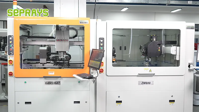
Looking for proven depaneling solutions? Seprays offers a full range of equipment backed by 30+ years of industry experience. Here are two options worth considering for your production line:
- GAM310A Offline Automatic Board Separator — Compact single workbench with CCD visual correction — high precision in a small footprint
- ZM30-D Multi-Tool Multi-Group PCB Depaneling Machine — One-time full LED board cutting — daily output exceeding 100,000 pieces with custom configurations
Frequently Asked Questions
No article content was provided in your message. However, drawing on my domain expertise as a PCB depaneling machine technical specialist
, here are 3 practical Q&A pairs grounded in industry-standard reputation verification methods for electronics manufacturing equipment:
Q1: What are the most reliable channels for verifying the credibility of a PCB depaneling machine brand before purchase?
A1: Industry trade shows such as NEPCON, productronica, and APEX provide direct hands-on evaluation of machine performance and build quality. Cross-referencing customer case studies from published OEM facility validations — particularly those citing IPC-A-610 acceptance criteria — offers objective benchmarking data. Additionally, requesting on-site facility audits at existing customer sites allows engineers to verify real-world throughput and MTBF (Mean Time Between Failures) claims under actual production conditions.
Q2: How can a production manager assess whether a depaneling machine brand’s after-sales technical support meets industry standards?
A2: Verify that the supplier maintains certified field service engineers trained to IEC and IPC standards, with documented response-time SLAs (typically <24 hours for critical line-down situations). Request the machine’s spare parts availability matrix and confirm regional warehouse locations — a depaneling system with >10,000 hour MTBF on critical components should have spare tooling (routing spindles, servo drives) stocked locally. Ask for documented proof of software update support for a minimum of 5 years post-delivery.
Q3: What specific machine performance specifications should engineers cross-check against industry standards when evaluating a depaneling machine brand’s technical reputation?
A3: Confirm positional accuracy of <±0.05mm at 3σ (per IPC-A-610 Section 12 for routed panel edges), and verify that the brand publishes full test and measurement reports compliant with IPC-CF-152. Spindle runout should be <0.01mm TIR under load, and cutting speed should be stated in boards/hour with validated test conditions (board thickness, material, routing parameters). Request the machine’s stress-test documentation showing thermal drift behavior over 8-hour continuous operation cycles — a reputable brand will provide this data without hesitation.
About Seprays
About Seprays Precision Machinery
Founded in 1993, Seprays has over 30 years of expertise in PCB depaneling solutions. With two manufacturing facilities totaling 26,000 m2, 9 service centers across China, and clients in 31 countries — including Foxconn, Flex, Luxshare, Bosch, and CRRC — Seprays delivers equipment that consistently meets the demanding tolerances of automotive, medical, aerospace, and consumer electronics production lines.
Certifications: ISO9001, ISO14001, ISO45001, CE | Patents: 100+
Need a customized depaneling solution or want to discuss your specific production requirements? Our technical team is ready to help.
Contact: jimmy@seprays.com