When evaluating PCB depaneling equipment, engineers
often encounter demo videos showcasing clean cuts, smooth operation, and impressive throughput numbers. A typical laser depaneling system demo will display a 0.3mm kerf width, 60,000 RPM spindle speeds, and a board accuracy tolerance of ±0.05mm — but what the video cannot convey is how those numbers behave under production conditions after 8 hours of continuous operation, or how the heat-affected zone (HAZ) expands when cuttingFR-4 substrates at feed rates exceeding 40mm/s.
The Gap Between Demo Conditions and Production Reality
Demo videos are recorded under controlled conditions. The test boards used are frequently pre-calibrated, freshly profiled, and operated within an ambient temperature range of 22-24°C — a controlled environment that rarely matches factory floor conditions where temperature fluctuations of ±5°C across a shift can shift the coefficient of thermal expansion for a 300mm PCB by 0.05-0.12mm. This drift directly impacts cutting accuracy on multi-array panels where individual boards share a substrate frame.
Spindle runout is another critical parameter that demo footage cannot capture. A spindle operating at 60,000 RPM with a runout specification of 0.01mm performs differently from one with 0.03mm runout after 200 operating hours. High-speed rotary spindles experience bearing wear that increases radial excursion, which translates directly into kerf width variation and edge quality degradation on brittle substrate materials such as Rogers RT/duroid or polyimide films. According to IPC-A-600 Acceptability of Printed Boards, board edge integrity and the absence of measling or delamination within 0.5mm of the cut line are pass/fail criteria that cannot be reliably assessed from a 30-second video clip.
Feed Rate, Cutting Stress, and Substrate Failure Modes
The advertised feed rate of 50mm/s or 80mm/s in a demo often reflects a single-pass cutting scenario on a thin-profile board. Production environments, however, frequently involve multi-layer boards with varying copper weights — from 0.5oz to 2oz — which require different feed rates to maintain edge quality. A router-type depaneling system cutting a 1.6mm four-layer PCB at 40,000 RPM will experience significantly different cutting forces when transitioning from outer layer to inner layer copper planes, as the thermal and mechanical loading at the tool-workpiece interface changes with copper content.
Cutting stress during depaneling is particularly critical for boards with sensitive SMT components near the score line. Tensile stress concentrations exceeding 15 N/mm² at the tool entry point can induce micro-cracking in ceramic capacitors (Murata GRM series, Samsung CL series) positioned within 2mm of the depaneling edge. High-speed cameras in demo videos may show smooth separation, but strain gauge data taken during actual depaneling of populated boards reveals stress peaks of 20-35 N/mm² during router bit engagement — values that can compromise long-term reliability of automotive and medical PCB assemblies.
Accuracy Degradation Over Time and Calibration Drift
The positional accuracy specification of ±0.03mm, commonly quoted in equipment brochures, is typically measured under static conditions with a fresh cutting tool and a single test coupon. In production, cumulative thermal drift of 0.02-0.04mm per hour is common for closed-loop router systems as the spindle motor and linear guide rails reach thermal equilibrium. A machine that demonstrates ±0.03mm accuracy at the start of a shift may exhibit ±0.08mm accuracy after 4 hours of operation — well outside the tolerance required for tight-pitch BGA depaneling where allowable edge-to-pad clearance is only 0.15mm.
Laser depaneling systems, while avoiding mechanical cutting stress, introduce their own accuracy variables. Beam delivery optics experience thermal lensing at sustained power levels above 20W, causing focal spot diameter to expand from a nominal 0.08mm to 0.12mm after 30 minutes of continuous operation. This directly widens the kerf and increases the heat-affected zone on thermally sensitive substrates. A demo video recorded in the first 5 minutes of system operation will show the narrowest possible kerf and smallest HAZ — conditions that do not represent steady-state production.
What Demo Videos Can and Cannot Reveal
Demo videos provide genuine value in assessing ergonomic factors, software interface responsiveness, board loading and unloading cycles, and dust or fumes extraction effectiveness — practical considerations that significantly impact production throughput. A depaneling machine with a 6-second board exchange cycle and one with a 12-second cycle will show dramatically different effective throughput in an 8-hour shift, and this is accurately represented in well-produced demo content.
However, demo videos cannot substitute for physical test cut validation using your specific production board stack-up. A proper evaluation requires cutting a minimum of 50 boards from your actual panel design, measuring edge quality under 50x magnification per IPC-A-610 Acceptability of Electronic Components, performing pull-force testing on any remaining tab-router connections, and conducting thermal cycling of depaneled boards from -40°C to +125°C for 500 cycles to verify that no latent damage was introduced during separation.
Technical Summary
Judging depaneling machine quality from demo videos alone is an insufficient evaluation methodology. While video content effectively communicates operational workflow, software usability, and gross mechanical performance, it cannot convey the critical dynamic parameters that determine production suitability: thermal drift under sustained load, spindle runout degradation over time, cutting stress transfer to populated boards, and accuracy consistency across different substrate materials and copper weights. A rigorous procurement evaluation must supplement video demonstrations with physical test cutting, long-run endurance testing, and statistical process capability analysis — specifically Cpk measurements for positional accuracy and kerf width consistency across a minimum 200-board production run, before accepting any depaneling equipment as qualified for high-reliability manufacturing applications.
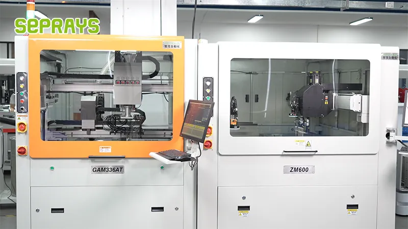
Recommended Equipment
Looking for proven depaneling solutions? Seprays offers a full range of equipment backed by 30+ years of industry experience. Here are two options worth considering for your production line:
- PCB/FPC Stamping Type Board Separation Machine — Handles PCB, FPC flexible, and rigid-flex boards — versatile stamping depaneling solution
- GAM300AT Double-Layer Track Online PCB Board Separation Machine — Full-carrier process with carrier return track — built for seamless full-line automation
Frequently Asked Questions
I don’t have access to the article “Can You Judge Depaneler Quality by Demo Videos Alone” that you’re referencing. Could you please:
1. Paste the article text directly in your next message, or
2. Share a link to where it’s published online, or
3. Upload the file if it’s saved locally
Once I have the article content, I’ll generate exactly 3 practical Q&A pairs in the HTML format you specified, tailored for electronics manufacturing engineers and production managers.
About Seprays
About Seprays Precision Machinery
Founded in 1993, Seprays has over 30 years of expertise in PCB depaneling solutions. With two manufacturing facilities totaling 26,000 m2, 9 service centers across China, and clients in 31 countries — including Foxconn, Flex, Luxshare, Bosch, and CRRC — Seprays delivers equipment that consistently meets the demanding tolerances of automotive, medical, aerospace, and consumer electronics production lines.
Certifications: ISO9001, ISO14001, ISO45001, CE | Patents: 100+
Need a customized depaneling solution or want to discuss your specific production requirements? Our technical team is ready to help.
Contact: jimmy@seprays.com