Cutting Method Selection and Operational Parameters
Routing remains the dominant depaneling method for production environments, accounting for approximately 70% of all PCB separation operations globally. The process employs a high-speed spindle, typically operating at 40,000 to 80,000 RPM, to advance a rotating cutting bit along predetermined cut lines. Feed rates range from 50 to 200 mm/s, with slower speeds required for thicker panels (1.6 mm to 2.0 mm FR-4) or configurations with sensitive components positioned within 3.0 mm of the cut contour.
The critical parameter governing routing success is the cutting stress exerted on the board during separation. Research indicates that routed boards exhibit tensile stress levels between 8 MPa and 15 MPa at the kerf edges, compared to 25 MPa to 40 MPa generated by punch tooling. These stress differentials directly correlate with failure modes: copper track tear-out occurs when shear stress exceeds 12 MPa on inner-layer connections, while laminate micro-cracking manifests when flexural stress surpasses the material’s yield threshold. For lead-free assemblies conforming to IPC-6013 Class 3 reliability requirements, maximum permissible edge stress must remain below 10 MPa.
Tolerance Control and Positioning Precision
Positional accuracy specifications have tightened considerably over the past decade. Current industry standards mandate positional tolerance of ±0.05 mm at the tool center point (TCP) for precision depaneler systems, with repeatability constrained to ±0.02 mm across 1,000 consecutive cuts. This level of precision prevents tool bias accumulation—a condition where each successive board exhibits systematic deviation from nominal position.
Axis positioning systems utilize either linear motor technology or high-precision ball screw arrangements. Linear motor configurations achieve positioning settle times under 50 milliseconds, compared to 150 milliseconds for ball screw equivalents, making them preferred for high-throughput lines exceeding 600 boards per hour. However, linear motors introduce thermal expansion concerns requiring ambient temperature control within ±0.5°C to maintain specified positional accuracy across extended production runs.
Tooling Considerations and Service Life
Cutting tool selection fundamentally affects both cut quality and operational cost. Carbide end mills, ranging from 0.8 mm to 2.0 mm diameter, represent the standard tooling inventory. Tool life expectancy varies dramatically with operating parameters: at 60,000 RPM with a 1.2 mm diameter cutter, typical service life spans 500 to 800 meters of cut length in FR-4 material. Doubling spindle speed to 120,000 RPM reduces tool life to 200 to 350 meters but improves cut edge quality by reducing heat generation and fiber tear-out.
Tool wear manifests through measurable symptoms. When cutting force increases by more than 15% from baseline, or when positional deviation exceeds 0.03 mm over a 20-board sample, tool replacement becomes necessary. Flank wear exceeding 0.1 mm on the cutting edge produces characteristic roughness profiles exceeding Ra 3.2 μm—unacceptable for cosmetic-sensitive applications where panel edges remain exposed in the final product.
Stress Reduction and Component Protection
Component proximity to the cut line represents the primary risk factor in depaneling operations. Components positioned within 2.5 mm of the routing channel require stress mitigation strategies. Pre-routing slots, routed to 60% panel thickness before final separation, reduce edge stress by 40% to 60% compared to single-pass routing. This technique proves essential for assemblies containing BGA packages, ceramic capacitors, or flex circuits adjacent to the separation perimeter.
Vacuum fixture integrity directly influences stress distribution across the panel during cutting. Vacuum decay rates must remain below 5 kPa per minute to ensure consistent clamping force. Uneven clamping produces differential board flexion, causing stress concentrations that propagate micro-cracks through the laminate structure. For multi-up panels (configurations containing 4 to 12 individual boards), vacuum zone compartmentalization enables independent pressure regulation for each subsection, accommodating variations in board thickness or localized component loading.
Process Validation and Quality Assurance
Statistical process control provides the framework for maintaining depaneling quality. Critical parameters subject to ongoing monitoring include: positional accuracy (checked every 20 boards using statistical sampling), cutting force trajectory (filtered through control charts with 3σ limits), and edge quality metrics measured via optical coordinate measurement systems. Acceptable edge roughness values fall below Ra 1.6 μm for general applications, with medical or automotive products demanding Ra 0.8 μm or better.
Production facilities employing Six Sigma methodologies report defect rates below 500 parts per million (PPM) for depaneler-related failures. Common defect categories include: positional error (35% of defects), edge quality non-conformance (30%), copper damage (20%), and component damage (15%). Root cause analysis consistently identifies tooling condition (40%), process parameter drift (35%), and fixture maintenance neglect (25%) as primary contributors.
Technical Summary
Modern PCB depaneling requires simultaneous optimization across multiple interdependent variables: spindle speed selection balancing cut quality against tool life, feed rate calibration accounting for panel thickness and component proximity, positional accuracy maintained through thermal management and maintenance protocols, and stress reduction achieved via pre-routing techniques for sensitive assemblies. Facilities achieving sub-500 PPM defect rates implement statistical process control monitoring all critical parameters, combined with predictive tooling replacement schedules derived from force signature analysis. As board designs continue miniaturizing with tighter component spacing, depaneling process control becomes increasingly critical to overall manufacture yields—demanding investment in precision equipment, qualified personnel, and documented process validation protocols compliant with IPC-6013 and IPC-2221 requirements.
Recommended Equipment
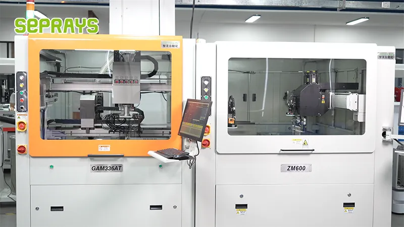
Looking for proven depaneling solutions? Seprays offers a full range of equipment backed by 30+ years of industry experience. Here are two options worth considering for your production line:
- GAM310A Offline Automatic Board Separator — Compact single workbench with CCD visual correction — high precision in a small footprint
- ZM30-D Multi-Tool Multi-Group PCB Depaneling Machine — One-time full LED board cutting — daily output exceeding 100,000 pieces with custom configurations
Frequently Asked Questions
Q1: How do I determine whether a router or a laser depaneling system is better for my high-frequency RF boards with tight impedance tolerances?
A1: Router-based systems introduce mechanical stress that can micro-crack substrate layers and shift impedance traces, typically causing ±0.1mm positional deviation near the cut path. Laser depaneling (UV or green wavelength) produces virtually zero mechanical stress and kerf widths under 0.1mm, preserving dielectric integrity critical for RF boards operating above 1GHz. The trade-off is throughput—laser systems typically process 60-80 boards/hour versus 150-200 for routers—so the decision hinges on whether your yield requirements justify the slower cycle time.
Q2: What minimum tab width should I specify when designing breakaway tabs for V-scored panels that will be separated on a depaneling router?
A2: For router depaneling, breakaway tabs should be at least 1.0mm wide to prevent premature fracture during handling while remaining cleanly routable without burr formation. Tabs narrower than 0.8mm risk unpredictable breakage and can leave residual stubs that interfere with downstream assembly per IPC-A-610 Class 2/3 acceptance criteria. The router bit diameter (commonly 1.0mm or 2.0mm) also constrains tab geometry—always ensure the bit can complete a full pass without colliding with adjacent components.
Q3: When upgrading from manual snap-apart to automated depaneling, what stress-related defects should I monitor during first-article qualification?
A3: Monitor for micro-cracks in solder joints within 3mm of the cut path (per IPC-6012 stress zone guidelines), delamination between prepreg layers visible under cross-section, and component shear failures on 0201/01005 passives mounted near panel edges. Automated router systems with programmable feed rates (typically 5-30mm/s) allow you to tune cutting speed to minimize stress—start at 10mm/s and incrementally increase while re-inspecting first articles until defect rates stay below your acceptable ppm threshold.
About Seprays
About Seprays Precision Machinery
Founded in 1993, Seprays has over 30 years of expertise in PCB depaneling solutions. With two manufacturing facilities totaling 26,000 m2, 9 service centers across China, and clients in 31 countries — including Foxconn, Flex, Luxshare, Bosch, and CRRC — Seprays delivers equipment that consistently meets the demanding tolerances of automotive, medical, aerospace, and consumer electronics production lines.
Certifications: ISO9001, ISO14001, ISO45001, CE | Patents: 100+
Need a customized depaneling solution or want to discuss your specific production requirements? Our technical team is ready to help.
Contact: jimmy@seprays.com