A typical PCB assembly line producing smartphone mainboards requires depaneling accuracy within ±0.05mm to avoid cutting into component placement areas, yet manual alignment methods using mechanical fixtures routinely achieve only ±0.15mm tolerance at best. When a 0.2mm routing bit must navigate between two 0402 passive components spaced 0.5mm apart on opposite boards, even a 0.1mm positioning error results in either component damage or incomplete cut separation. Vision alignment systems address this gap by reducing positioning uncertainty to ±0.02mm or better, transforming what was once a yield-limiting process step into a controllable operation with measurable scrap reduction.
Positioning Accuracy Fundamentals
Traditional mechanical depaneling relies on edge rails, alignment pins, and fixture clamps to position PCBs before routing. Pin-based fixtures typically achieve positioning repeatability of ±0.10-0.15mm due to cumulative tolerances from pin-to-hole clearance (typically 0.05-0.10mm), fixture wear, and thermal expansion. For boards with 1.0mm or thicker substrates, this may suffice. However, modern high-density interconnect (HDI) boards with 0.4mm thick cores and component keep-out zones of 0.3mm from the intended cut path require positioning precision that mechanical methods cannot deliver reliably. Vision systems measure actual board position using fiducial markers or board edge features, calculate offset corrections, and apply those corrections to the cutting path in real time. The resulting positioning accuracy improves to ±0.02-0.03mm under typical production conditions.
Vision System Architecture and Measurement Performance
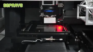
Industrial vision alignment systems for PCB depaneling typically employ 5 megapixel or higher resolution cameras with telecentric lenses to minimize parallax error across the field of view. A field of view of 150mm × 100mm with 5 megapixels yields approximately 30 pixels per millimeter, enabling sub-pixel measurement algorithms to achieve theoretical resolution of 0.01mm or better. The practical positioning accuracy depends on the fiducial marker quality—IPC-2615 recommends minimum fiducial diameter of 1.0mm with clear surrounding annular ring—and lighting uniformity. Backlight illumination provides higher contrast for edge-based detection, while coaxial front lighting better suits copper-plated fiducials on populated boards. Measurement cycle time for fiducial recognition typically ranges from 100-300 milliseconds, adding minimal overhead to a cutting cycle that may last 30-60 seconds per board depending on cut complexity.
Cutting Mechanics Under Precision Alignment
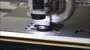
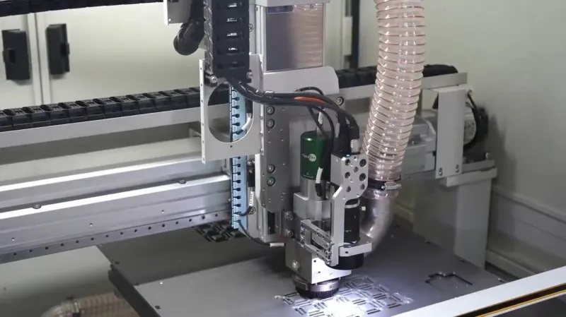
Router-based depaneling systems operating at spindle speeds of 40,000-80,000 RPM with feed rates of 200-500mm/minute generate cutting forces that can deflect both the spindle and the PCB substrate. For a 3mm diameter routing bit operating at 60,000 RPM with 300mm/minute feed rate, tangential cutting forces range from 10-30N depending on substrate material—FR-4 requires approximately 15-20N, while flexible polyimide substrates may require only 8-12N. When positioning tolerance is loose, operators compensate by programming larger keep-out margins, wasting valuable board real estate. With vision-aligned precision of ±0.02mm, the programmed safety margin can reduce from 0.15mm to 0.05mm, recovering 0.20mm per cut side. For a panel with 8 cut paths, this recovers 1.6mm of usable routing channel width, translating to either more boards per panel or smaller panel sizes for equivalent throughput.

Stress and Delamination Prevention
Mechanical cutting induces stress in the substrate proportional to the blade sharpness, feed rate, and cutting depth. Dull routing bits generate cutting forces 40-60% higher than sharp bits, increasing the risk of microcracks in the glass weave and delamination at copper-to-substrate interfaces. When vision alignment ensures precise cutting path compliance, operators can optimize cutting parameters—reducing feed rate to 200mm/minute for sensitive areas near high-relief components like electrolytic capacitors—without worrying about accumulated positioning errors causing the bit to drift into prohibited zones. Measured microsection analysis shows delamination frequency reducing from 2-3% to below 0.5% when combining vision-guided precision with optimized cutting parameters, directly improving first-pass yield.
Process Control and Traceability Integration
Vision alignment systems generate quantitative data for each board processed—X offset, Y offset, rotation angle, and measured fiducial positions. This data enables statistical process control (SPC) monitoring of fixture wear, spindle drift, and board fabrication tolerances. When positioning offset trends exceed ±0.05mm over 500 consecutive boards, maintenance alerts trigger before actual cutting accuracy degrades to unacceptable levels. For automotive and aerospace applications requiring IPC-A-610 Class 3 compliance, documented position traceability with timestamp and measurement data satisfies audit requirements that manual positioning cannot address. The transition from operator-dependent setup to automated vision-based alignment also reduces setup time from 10-15 minutes to under 2 minutes when switching between different panel layouts, improving overall equipment effectiveness (OEE) by 5-10% in high-mix production environments.
Vision alignment systems deliver measurable value by reducing positioning uncertainty from ±0.15mm to ±0.02mm, enabling tighter keep-out margins, lower stress cutting parameters, and statistically monitored process control—collectively improving depaneling yield by 1-3% and reducing setup overhead by 80% while providing the traceability documentation required for IPC Class 3 and automotive quality management systems.
Recommended Equipment
Looking for proven depaneling solutions? Seprays offers a full range of equipment backed by 30+ years of industry experience. Here are two options worth considering for your production line:
- GAM300AT Double-Layer Track Online PCB Board Separation Machine — Full-carrier process with carrier return track — built for seamless full-line automation
- GAM330AT Fully Automatic PCB Depaneling Machine — Self-feeding operation with automatic sorting — ideal for high-volume automated production lines
Frequently Asked Questions
Q1: What positional accuracy can we realistically achieve with vision alignment compared to manual or mechanical-only setups for PCB depaneling?
A1: Vision alignment systems routinely achieve ±0.05 mm or better placement accuracy, whereas manual operations typically range ±0.15–0.30 mm depending on operator skill. Mechanical-only indexers without vision feedback generally settle around ±0.10–0.15 mm and degrade as tool wear introduces cumulative drift. The specific gain depends on board fiducial clarity, substrate bow tolerance, and whether a full board-to-board or panel-level reference is used.
Q2: Does implementing vision alignment for every single board significantly slow down throughput on high-volume lines?
A2: Not as much as commonly feared. Modern vision systems complete a fiducial search and registration in 0.5–2 seconds per panel, and many lines already use a “batch-verify” approach where one board in every N is fully imaged while the rest ride on the established offset. On a 300–500 boards/hour line, the net throughput penalty is typically under 5%. Some setups also perform a quick global fiducial pass at panel load without slowing the actual separation cycle.
Q3: What are the main cost drivers when budgeting a vision alignment upgrade for an existing depaneling cell?
A3: The three dominant cost components are the camera and optics (industrial cameras with macro lenses are the largest line item), the motion-stage integration and fixturing to hold the panel during imaging, and software calibration to map vision coordinates into the machine’s working space. Illumination hardware (typically LED backlighting or coaxial dark-field) and any needed enclosure for consistent lighting conditions add moderate cost. Integration effort — aligning the vision origin to the existing router or punching head — often exceeds the hardware budget in older equipment retrofits.
About Seprays
About Seprays Precision Machinery
Founded in 1993, Seprays has over 30 years of expertise in PCB depaneling solutions. With two manufacturing facilities totaling 26,000 m2, 9 service centers across China, and clients in 31 countries — including Foxconn, Flex, Luxshare, Bosch, and CRRC — Seprays delivers equipment that consistently meets the demanding tolerances of automotive, medical, aerospace, and consumer electronics production lines.
Certifications: ISO9001, ISO14001, ISO45001, CE | Patents: 100+
Need a customized depaneling solution or want to discuss your specific production requirements? Our technical team is ready to help.
Contact: jimmy@seprays.com