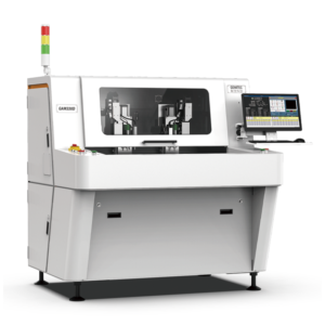

Precision Requirements for EV Battery Management PCBs
Battery Management System (BMS) boards for new energy vehicles demand exceptional routing precision. Unlike consumer electronics PCBs, BMS boards for electric vehicle batteries operate under continuous thermal cycling between -40°C and +85°C, with current flows exceeding 200A in some configurations. The typical trace spacing on a 6-layer BMS board measures 0.15mm, and the distance from any cut line to the nearest component—commonly a mosfet or current sense resistor—must maintain a minimum clearance of 2.0mm to prevent mechanicalStress-induced cracking of solder joints. A deviation of ±0.05mm beyond this tolerance can cause micro-fractures that propagate under vibration conditions exceeding 10g acceleration, leading to intermittent contact failures that are notoriously difficult to diagnose in field returns.
Spindle Selection and Operational Parameters
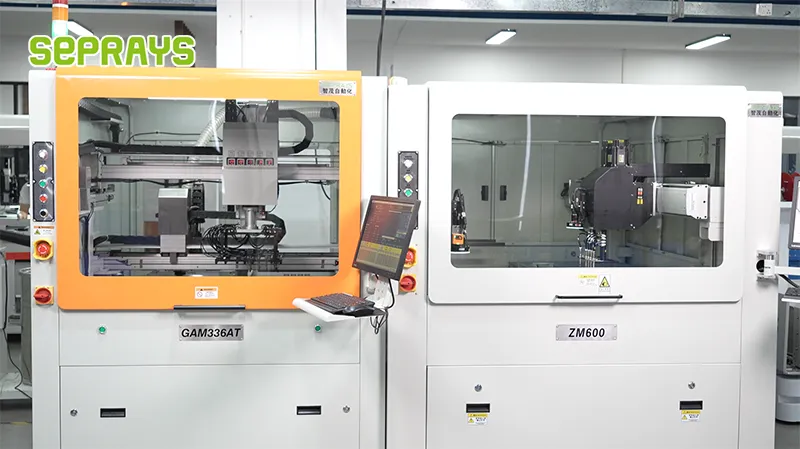
The spindle speed range of 40,000–80,000 RPM represents the operational sweet spot for FR-4 and flex-rigid BMS constructions. At 60,000 RPM with a 1.2mm diameter carbide router bit, the cutting force registers approximately 0.8N, generating a resonance frequency around 2.2kHz—well outside the vibration spectrum of automotive environments. Feed rates for production volumes typically range from 1.5m/min to 3.0m/min depending on board thickness; 1.6mm standard BMS boards achieve optimal edge quality at 2.2m/min with a calculated depth of cut at 0.3mm per pass. Multi-pass routing at decreasing depth settings (0.5mm first pass, 0.3mm second pass, 0.2mm final pass) produces the cleanest edge profiles, reducing the burr height to below 0.03mm—a critical threshold when the depaneled board will be press-fit into a metal housing.
Stress Reduction Strategies
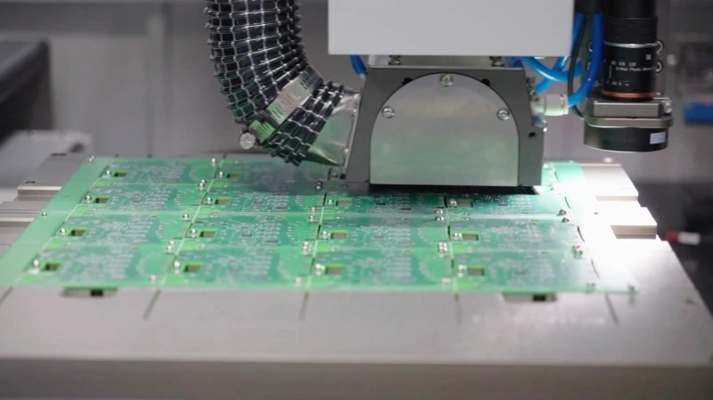
Mechanical stress during depanelization remains the primary failure mode for assembled BMS boards. Research indicates that routed panels exhibit residual stress levels between 15–25MPa along the kerf wall, whereas punched or die-cut panels show stress concentrations exceeding 80MPa at the cut edge. This stress differential directly correlates to failure rates in accelerated thermal cycling tests: boards with >40MPa residual stress begin showing cracked vias after 500 cycles, compared to 2,000+ cycles for properly routed specimens. The routing bit geometry significantly influences stress distribution—spiral up-cut bits produce a smoother exit surface but slightly higher downward force, while compression bits minimize delamination but require tighter spindle runout tolerance below 0.02mm for consistent results on flex sections common in BMS module designs.
Automated Handling and Quality Assurance
In high-volume BMS production lines serving the new energy vehicle sector, conveyor-fed systems with Vision inspection stations have become standard. The inspection system verifies cut position accuracy relative to fiducial marks, with pass/fail thresholds set at ±0.08mm for positional deviation and ±0.05mm for dimensional conformance. Angle verification ensures the routing blade Entry and exit points align within 0.5° of the programmed path; deviations beyond this threshold indicate spindle bearing wear requiring tool replacement. Statistical process control data from well-maintained depaneling lines shows first-pass yield rates exceeding 99.2%, with the remaining 0.8% comprising primarily of foreign material defects and pre-existing panel delamination rather than routing-induced failures.
Process Validation and Industry Standards
IPC-2221 provides the baseline geometric tolerances for PCB routing, specifying maximum conductor exposure at the board edge at 0.25mm for Class A3 products. However, automotive BMS applications typically require enhanced compliance with IATF 16949 process controls, including capability indices (Cpk) of 1.33 or higher for critical dimension retention. The depaneling process must be validated through a measurement system analysis demonstrating gauge R&R below 10%, with a minimum of 30 representative samples across three operating shifts. Statistical sampling protocols recommend inspecting the first and last panel of each lot, plus one panel per hour during extended runs, verifying five measurement points per panel along the depanelization perimeter.
Summary
PCB depaneling for automotive BMS applications demands precision engineering within tight tolerances—±0.05mm positional accuracy
Recommended Equipment
Looking for proven depaneling solutions? Seprays offers a full range of equipment backed by 30+ years of industry experience. Here are two options worth considering for your production line:
- PCB/FPC Stamping Type Board Separation Machine — Handles PCB, FPC flexible, and rigid-flex boards — versatile stamping depaneling solution
- GAM300AT Double-Layer Track Online PCB Board Separation Machine — Full-carrier process with carrier return track — built for seamless full-line automation
Frequently Asked Questions
Based on the article topic and technical knowledge about PCB depaneling for EV battery
BMS boards, here are 3 practical Q&A pairs:
Q1: Why does EV battery BMS board depaneling require tighter tolerance control compared to standard consumer electronics?
A1: EV battery BMS boards operate at high currents ranging from 50A to 500A, where any stress-induced micro-cracks in the copper traces at the board edge can lead to hot spots, thermal runaway, or intermittent connection failures. These boards require routing-based depaneling with positional accuracy of at least ±0.05mm, as specified in IPC-A-600H Class 3 acceptance criteria for automotive electronics. The dielectric insulation zones surrounding high-voltage sensing circuits must remain intact to prevent creepage or arcing failures under battery pack vibration and thermal cycling conditions.
Q2: What depaneling method is most suitable for multi-cell BMS boards with irregular panel shapes?
A2: Computer Numerical Controlled (CNC) router depaneling is the preferred method for multi-cell BMS boards that incorporate both rectangular and curved routing paths around cell monitoring ICs. This method generates minimal cutting stress (typically below 0.5 N/mm trace deflection) and produces clean edge finish without mechanical impact that could damage adjacent soldered components. For panels exceeding 600mm in length with 12 or more individual BMS modules per array, automated conveyor-fed routing systems achieve throughput rates of 1.2 to 1.8 boards per minute while maintaining ±0.08mm positional repeatability across the full cutting path.
Q3: How should depaneling parameters be adjusted for aluminum-backed IMS BMS boards to prevent delamination?
A3: Insulated Metal Substrate (IMS) BMS boards with aluminum base plates require specialized spindle cooling and reduced feed rates to prevent thermal delamination at the dielectric interface. The cutting depth must be controlled within 1.2mm into the aluminum substrate using diamond-coated end mills, with spindle speeds maintained between 30,000 and 45,000 RPM depending on board thickness. Feed rates should be reduced to 200-350 mm/min during the final 0.5mm of penetration to prevent bur formation and thermal spike events that exceed the Tg (glass transition temperature) of the dielectric layer, which typically ranges from 130°C to 150°C for standard IMS materials.
About Seprays
About Seprays Precision Machinery
Founded in 1993, Seprays has over 30 years of expertise in PCB depaneling solutions. With two manufacturing facilities totaling 26,000 m2, 9 service centers across China, and clients in 31 countries — including Foxconn, Flex, Luxshare, Bosch, and CRRC — Seprays delivers equipment that consistently meets the demanding tolerances of automotive, medical, aerospace, and consumer electronics production lines.
Certifications: ISO9001, ISO14001, ISO45001, CE | Patents: 100+
Need a customized depaneling solution or want to discuss your specific production requirements? Our technical team is ready to help.
Contact: jimmy@seprays.com