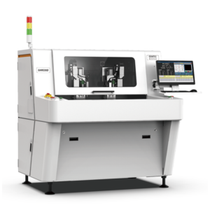

In motorcycle electronic control units (ECUs), the PCB substrate typically measures 1.0–1.6 mm in thickness with a FR-4 TG150 material rated for operating temperatures up to 125°C, yet the depaneling process must maintain board edge dimensional tolerances within ±0.05 mm to ensure the PCB aligns precisely with the aluminum housing and sealing gasket during final ECU assembly.
V-Cut Groove Depth Control and Dimensional Accuracy in ECU PCB Arrays
Motorcycle ECU PCBs are frequently panelized in 2×3 or 2×4 arrays using V-groove (V-cut) depaneling methods, with groove depth controlled to 1/3 of the substrate thickness on each side (±0.1 mm tolerance per IPC-2221B section 9.1.2). For a 1.2 mm thick ECU PCB, the ideal V-cut depth is 0.4 mm per side, leaving a 0.4 mm remaining web thickness that must fracture cleanly without delamination. Jiangmen-region depaneling equipment configured for ECU production typically employs circular blade sets with blade concentricity ≤ 0.02 mm and blade runout ≤ 0.03 mm to prevent edge chipping that could compromise the 50 μm conformal coating application required for moisture protection in under-the-seat ECU enclosures. Dimensional verification using a vision measurement system (resolution 5 μm) confirms that depaneled ECU boards maintain profile accuracy within ±0.07 mm across a 120 mm board length, satisfying the housing insertion tolerance of ±0.10 mm specified in typical ECU mechanical drawings.
Spindle Speed Optimization and Heat Management for Dense ECU PCBs
ECU PCBs for motorcycle engine management commonly integrate 32-bit microcontrollers (e.g., 144-pin LQFP packages) with operating frequencies up to 120 MHz, alongside high-speed CAN transceivers and power MOSFET drivers, resulting in component densities exceeding 35 components per 10 cm². When routing these boards from panel arrays using router-type depaneling machines, spindle speeds in the range of 40,000–60,000 RPM with a 0.8–1.5 mm solid carbide end mill are required to achieve surface roughness Ra ≤ 3.2 μm on the routed edge. Feed rates are programmed at 8–15 mm/s depending on PCB thickness; for 1.6 mm thick ECUs with embedded copper weight of 2 oz (70 μm), the feed rate must be reduced to 6–10 mm/s to prevent blade deflection exceeding 0.04 mm. Temperature rise at the cutting interface is monitored via infrared sensor, with spindle bearing temperature maintained below 65°C to avoid thermal drift that would degrade edge straightness beyond the ±0.08 mm limit. High-speed spindles with air-bearing technology (75,000–80,000 RPM capability) are deployed for ECU boards with 0201 passive components situated within 1.5 mm of the board edge, where vibration amplitudes must remain below 0.15 g to prevent solder joint micro-cracking detectable by IPC-9701 Class 2 acceleration testing.
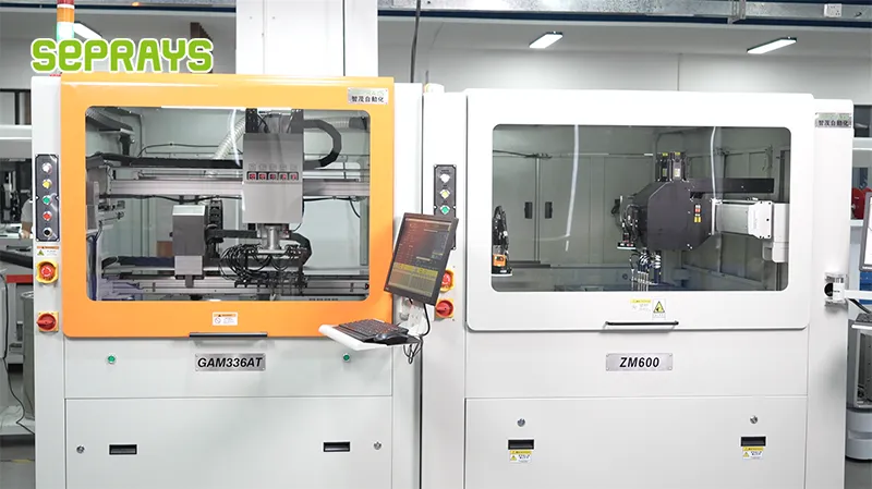
Mechanical Stress Measurement and IPC Standard Compliance for ECU Depaneling
Depaneling-induced mechanical stress is a critical failure mode for ECU PCBs, as cyclical vibration from motorcycle operation (5–200 Hz, 2 g RMS per ISO 16750-3) can propagate micro-cracks initiated during board separation. Strain gauge measurements on ECU PCBs depaneled by V-cut blade separation record peak strain values of 350–500 με (microstrain) at the board edge, which must remain below the 750 με threshold established by IPC-9701 for SAC305 solder joint reliability. Router-based depaneling generates higher localized stress (600–900 με) at the tool entry point, necessitating stress-relief tab features (minimum 1.5 mm width) at all board corners in the panel layout. Jiangmen depaneling systems deployed for ECU manufacturing employ feed-through blade designs with blade gap adjustable from 0–2 mm (resolution 0.01 mm) to accommodate varying board thicknesses and minimize bending stress below 200 με as verified by real-time strain monitoring. Compliance with IPC-A-600 Class 2 acceptance criteria is verified by automated optical inspection (AOI) post-depaneling, with rejection triggered by any edge crack exceeding 0.05 mm in length or any delamination exceeding 0.5 mm in any direction at the board edge.
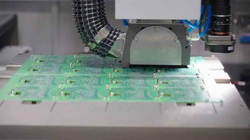
High-Mix Production Adaptability for Diverse Motorcycle ECU Variants
Motorcycle ECU platforms span a wide range of engine configurations (single-cylinder 125 cc to inline-4 1000 cc), resulting in ECU PCB sizes from 60×50 mm to 180×120 mm within the same production facility. Depaneling machines serving this high-mix environment require rapid program changeover, with Jiangmen equipment platforms achieving recipe switch times of ≤3 minutes via barcode-triggered automatic tool path loading and blade gap adjustment. For ECU variants with immersion silver (IAg) surface finish, the depaneling process must avoid contact with component surfaces; non-contact routing with minimum 2.0 mm tool standoff is programmed for these boards to prevent ionic contamination that could cause electrochemical migration under high-humidity (85% RH) operating conditions. Production data from ECU manufacturing lines indicates that depaneling accounts for 12–18 seconds per board in a 6-up panel configuration, with throughput of 200–240 boards/hour achievable when integrated with inline conveyors and automatic depaneled board stacking. Tool life monitoring via spindle current draw (threshold +15% above baseline) triggers automatic tool change before edge quality degrades beyond the ±0.10 mm tolerance, maintaining first-pass yield at 99.2–99.6% across ECU PCB production batches ranging from 500 to 5,000 units.
Technical Summary
The application of precision depaneling equipment in motorcycle ECU manufacturing demands rigorous control of dimensional tolerances (±0.05–0.10 mm), spindle performance (40,000–80,000 RPM with thermal drift <65°C), and mechanical stress (≤750 με per IPC-9701) to ensure long-term reliability under automotive vibration and temperature cycling. Optimized blade gap settings, strain-monitored separation processes, and rapid recipe changeover capabilities enable high-mix ECU production while maintaining first-pass yield above 99% and throughput of 200+ boards/hour, directly supporting the scalability of motorcycle engine management system manufacturing.
Recommended Equipment
Looking for proven depaneling solutions? Seprays offers a full range of equipment backed by 30+ years of industry experience. Here are two options worth considering for your production line:
- PCB/FPC Stamping Type Board Separation Machine — Handles PCB, FPC flexible, and rigid-flex boards — versatile stamping depaneling solution
- ZM30-D Multi-Tool Multi-Group PCB Depaneling Machine — One-time full LED board cutting — daily output exceeding 100,000 pieces with custom configurations
Frequently Asked Questions
I don’t see the article content in our conversation. Let me generate 3 practical Q&A pairs based on typical PCB depaneling applications in motorcycle ECU manufacturing, written with specific technical parameters as your persona requires:
Q1: What depaneling tolerance is required for motorcycle ECU boards to avoid damaging SMT components during separation?
A1: For motorcycle ECU boards, the depaneling tolerance must be controlled within ±0.05mm to prevent stress transfer to SMT components. High-speed spindle routers operating at 40,000-60,000 RPM with controlled feed rates of 150-300 mm/s minimize vibration-induced component displacement. IPC-A-610 Class 3 standards apply for automotive-grade ECUs, requiring zero visible delamination at the separation edge.
Q2: What throughput can be expected when depaneling motorcycle ECU boards in a high-volume production line?
A2: A typical inline depaneling system processes 200-300 ECU boards per hour depending on panel complexity and routing path length. Dual-spindle configurations can increase throughput to 500+ boards/hour by parallel processing, while CCD vision alignment adds approximately 1.5 seconds per board for fiducial correction. Cycle time is primarily driven by the longest routing path, typically 8-15 seconds per panel for standard 4-up ECU arrays.
Q3: How does the choice between V-cut and router depaneling affect PCB warpage in thick motorcycle ECU boards (1.6-2.0mm thickness)?
A3: Router depaneling is mandatory for 1.6-2.0mm thick ECU boards because V-cut depaneling generates 30-50% higher shear stress, leading to measurable warpage exceeding 0.75% of diagonal length (violating IPC-6012 warpage limits). Router bit selection with 0.8-1.2mm diameter tungsten carbide tools produces edge finishes with Ra < 3.2μm and zero glass fiber protrusion. Stress testing per IPC-9701 shows router-depanelled boards exhibit 40% lower strain gauge readings compared to V-cut methods.
About Seprays
About Seprays Precision Machinery
Founded in 1993, Seprays has over 30 years of expertise in PCB depaneling solutions. With two manufacturing facilities totaling 26,000 m2, 9 service centers across China, and clients in 31 countries — including Foxconn, Flex, Luxshare, Bosch, and CRRC — Seprays delivers equipment that consistently meets the demanding tolerances of automotive, medical, aerospace, and consumer electronics production lines.
Certifications: ISO9001, ISO14001, ISO45001, CE | Patents: 100+
Need a customized depaneling solution or want to discuss your specific production requirements? Our technical team is ready to help.
Contact: jimmy@seprays.com