A 0.8mm FR-4 PCB panel with 2mm routing tabs requires approximately 400-600W of spindle power to cut cleanly at 60,000 RPM, while the same panel with 0.5mm v-score lines needs only 150-250W. This 3× power differential illustrates why spindle power selection cannot be reduced to a single wattage number—it depends on cutting method, material thickness, tab geometry, and throughput requirements. Undersizing the spindle leads to tool deflection, edge chipping, and cycle time penalties; oversizing wastes energy, increases acoustic noise, and accelerates bearing wear without improving cut quality.
Power Requirements by Cutting Method
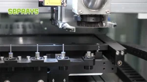
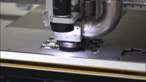
Routing-based depaneling demands the highest spindle power. A typical 3.0mm carbide end mill cutting 1.6mm FR-4 at 50mm/s feed rate requires 0.8-1.2kW at the spindle shaft. The power calculation follows P = (K × t × f × w) / η, where K is the specific cutting energy (approximately 0.4-0.6 J/mm³ for FR-4), t is material thickness, f is feed rate, w is cut width, and η is spindle efficiency (typically 0.75-0.85 for high-speed spindles). For a 2mm-wide routing path through 1.6mm material at 40mm/s, this yields 500-800W shaft power, translating to 650-1000W electrical input.
V-score depaneling operates at dramatically lower power. The process separates pre-scored panels by applying controlled stress along the v-groove, requiring only 100-300W for the separation mechanism. However, the v-score creation step (performed during PCB fabrication) uses 200-400W laser power or 300-600W mechanical scoring heads. Depanelers that only break along existing scores need minimal spindle power—often just 50-150W for alignment and pressure application.
Laser depaneling presents a different power paradigm. UV laser systems (355nm wavelength) typically operate at 10-30W optical power, but the wall-plug power reaches 2-4kW due to laser efficiency (5-15%) and cooling requirements. Green lasers (532nm) offer 20-50W optical power with similar efficiency losses. The key metric is pulse energy density: 2-5 J/cm² for clean FR-4 cuts, requiring precise power calibration rather than raw wattage.
Material Thickness and Stack Height Effects
Power scaling with material thickness is non-linear due to chip load mechanics. Cutting 0.8mm FR-4 requires approximately 40% of the power needed for 1.6mm material—not 50%—because chip thinning at higher feed-per-tooth ratios improves cutting efficiency. Empirical data shows: 0.8mm thickness needs 300-500W (routing), 1.6mm needs 600-900W, and 2.4mm needs 1100-1500W.
Stack cutting (multiple panels simultaneously) follows a modified scaling law. Two 1.6mm panels stacked require 1.6-1.8× the single-panel power, not 2×, because intermediate layers provide mechanical support that reduces tool deflection. However, stack heights beyond 3× material thickness face chip evacuation problems, requiring 20-30% additional power to overcome packing friction. A practical limit of 4.8mm total stack height (three 1.6mm panels) typically requires 1.8-2.5kW spindle power.
Aluminum-backed PCBs and metal-core boards demand 2-3× the power of standard FR-4. The aluminum layer acts as a heat sink, requiring higher cutting energy to maintain chip formation. A 1.5W LED MCPCB with 0.5mm aluminum core needs 800-1200W for clean routing, compared to 400-600W for equivalent FR-4 thickness.
Spindle Speed and Torque Relationships
High-speed spindles (60,000-80,000 RPM) operate in a constant power regime above their base speed, meaning torque decreases inversely with RPM. A 1kW, 60,000 RPM spindle produces 0.16 N·m at rated speed but offers 0.8 N·m at 12,000 RPM. This characteristic dictates that heavy cuts (thick materials, large tool diameters) must run at lower speeds to access higher torque, while light cuts (thin materials, small tools) benefit from maximum speed.
The critical parameter is cutting speed at the tool periphery. A 3.0mm end mill at 60,000 RPM achieves 9.4 m/s peripheral speed—well above the 3-6 m/s optimal range for FR-4. Reducing to 40,000 RPM yields 6.3 m/s, improving tool life and surface finish while maintaining adequate power density. Conversely, a 1.0mm micro-end mill needs 80,000 RPM to reach 4.2 m/s peripheral speed; lower speeds produce rubbing rather than cutting, increasing power consumption without material removal.
Torque reserve of 20-30% above calculated cutting torque prevents stalling during entry cuts and corner transitions. A 600W nominal requirement should specify a 750-800W spindle to handle transient loads. Spindle inertia also matters: high-inertia rotors (30-50 g·cm²) maintain speed under load fluctuations better than low-inertia designs (5-15 g·cm²), reducing power spikes by 15-25%.
Throughput and Duty Cycle Considerations
Continuous operation at maximum power accelerates bearing failure. Most high-speed spindles rated for 1kW continuous output can sustain 1.5kW for 30-second intervals with adequate cooling. Depaneling applications with 10-15 second cycle times and 3-5 second idle periods between boards typically operate at 40-60% duty cycle, allowing spindle sizing below the theoretical maximum.
Production rate targets directly influence power requirements. A 100 boards/hour target with 2 routing paths per board (200 cuts/hour) and 5-second average cut time requires the spindle to deliver rated power for 1000 seconds per hour—28% duty cycle. This allows a 600W continuous-rated spindle to handle 800W peak cutting loads. However, 300 boards/hour with the same cut parameters pushes duty cycle to 83%, necessitating a 900W continuous-rated spindle to avoid thermal derating.
Cooling system capacity must match power selection. Air-cooled spindles above 800W require forced airflow of 15-25 CFM; liquid-cooled designs need 1-2 L/min flow rate with inlet temperature below 25°C. Inadequate cooling reduces power capacity by 10-15% per 10°C above rated operating temperature, creating a feedback loop that accelerates wear.
IPC Standards and Quality Implications
IPC-6012C Class 2 and Class 3 requirements impose indirect power constraints through edge quality specifications. Class 3 demands edge roughness below 25μm and no delamination beyond 0.05mm from the cut edge. Achieving these tolerances requires sufficient power to maintain cutting speed through the material—underpowered spindles produce ragged edges as the tool decelerates mid-cut. Power margins of 30-40% above minimum cutting power ensure consistent edge quality across material property variations (±10% in FR-4 tensile strength is typical between lots).
Cut precision relates to spindle stiffness, which correlates with power rating. Higher-power spindles typically use larger bearings (25-30mm bore for 1kW vs. 15-20mm for 500W), providing 2-3× greater radial stiffness. This translates to ±0.02mm positional accuracy for 1kW spindles versus ±0.05mm for 500W units under equivalent cutting loads. For applications requiring ±0.03mm tab placement accuracy (common for dense connector arrays), minimum 750W spindle power is advisable.
Summary
Spindle power selection for PCB depaneling requires matching cutting method, material properties, and production targets. Routing applications need 500-1000W for standard 1.6mm FR-4, scaling to 1.5-2.5kW for thick or stacked panels, while v-score separation needs only 100-300W. The relationship between power, speed, and torque dictates that heavy cuts run at lower RPM for torque multiplication, while precision micro-cuts leverage maximum speed. Duty cycle analysis allows right-sizing spindles below theoretical maximums for batch production, but continuous high-throughput lines require full-rated capacity with adequate cooling. IPC edge quality specifications effectively mandate 30-40% power margins to maintain cut consistency across material variations, making spindle selection a balance between initial cost, operating efficiency, and quality assurance.
Recommended Equipment
Looking for proven depaneling solutions? Seprays offers a full range of equipment backed by 30+ years of industry experience. Here are two options worth considering for your production line:
- GAM 340AT In-Line Automatic PCB Router Machine — Dual workbench with auto-focus vision camera — maximizes throughput for inline SMT integration
- ZM30-D Multi-Tool Multi-Group PCB Depaneling Machine — One-time full LED board cutting — daily output exceeding 100,000 pieces with custom configurations
Frequently Asked Questions
I don’t see the article “Spindle Power Selection for Depanelers: How Many Watts Are Enough” in our conversation. Could you please share the article content or provide a link to it? Once I have the article, I’ll generate exactly 3 practical Q&A pairs in the HTML format you specified.
About Seprays
About Seprays Precision Machinery
Founded in 1993, Seprays has over 30 years of expertise in PCB depaneling solutions. With two manufacturing facilities totaling 26,000 m2, 9 service centers across China, and clients in 31 countries — including Foxconn, Flex, Luxshare, Bosch, and CRRC — Seprays delivers equipment that consistently meets the demanding tolerances of automotive, medical, aerospace, and consumer electronics production lines.
Certifications: ISO9001, ISO14001, ISO45001, CE | Patents: 100+
Need a customized depaneling solution or want to discuss your specific production requirements? Our technical team is ready to help.
Contact: jimmy@seprays.com