
Networking Scenarios of Inline Routers with Conveyors & Buffer Machines
When an SMT line
runs at 45 boards per minute with product changeover intervals under 8 minutes, the depaneling cell becomes the critical bottleneck that determines whether the entire line achieves its rated throughput. In high-mix manufacturing environments, an inline router networked with properly configured conveyors and buffer machines can maintain consistent cycle time delivery across shift boundaries, while a standalone depaneling cell typically exhibits ±12% cycle time variance due to manual feeding inconsistencies and upstream timing jitter.
Conveyor Integration and Synchronization Architecture
Modern inline routers communicate with upstream and downstream conveyor sections through encoder-based position tracking and event-driven signaling protocols. Each conveyor segment uses incremental rotary encoders with 600-1200 pulses per revolution to track belt position in real time, enabling the router controller to calculate board arrival time with ±50ms accuracy based on measured belt velocity. Position feedback loops maintain board spacing within ±3mm at speeds up to 0.8 m/min, which is critical because even 5mm of spacing variation at 40,000 RPM spindle speed can cause the routing tool to engage a board edge prematurely, generating particulate contamination or dimensional non-conformance.
The signaling interface between conveyor and router typically employs a combination of discrete I/O for basic handshaking (board-present, board-accepted, fault) and optional RS-485 or Ethernet/IP for extended telemetry. Most modern systems implement a producer-consumer messaging model where the conveyor controller publishes board identification data—including panel ID, lot code, and recipe number—consumed by the router for adaptive cutting parameter selection. This data exchange allows the same depaneling cell to transition between different panel thicknesses (0.8mm to 2.4mm FR-4) and stack configurations (single-board versus multi-up panels) without manual recipe adjustment, provided the conveyor network forwards the recipe linkage correctly.
Throughput Matching and Speed Profiling
The fundamental constraint in networked depaneling is matching the router’s cutting capacity—measured in cuts per minute at a given feed rate—to the conveyor’s board delivery rate. A 3mm aluminum-backed LED panel requires a feed rate of approximately 150-200mm/min with a 0.8mm carbide router bit to achieve clean kerf geometry without delamination, yielding a single-board cycle time of 12-18 seconds. When this is networked with a conveyor delivering boards every 5 seconds, a single router cannot sustain the line speed, making a dual-spindle or buffer-dependent configuration necessary.
Buffer machines resolve this throughput mismatch by decoupling the upstream and downstream line rates through staged accumulation. A FIFO (first-in-first-out) buffer with 15 storage positions can absorb a 3-minute period of elevated upstream throughput caused by a downstream equipment fault, then drain at the corrected rate once the fault clears. Buffer depth selection follows a simple engineering rule: buffer capacity (in board-positions) should equal the maximum expected fault recovery time (in seconds) multiplied by the line rate (boards per second). For a line rated at 60 boards per minute with a 90-second average fault recovery window, the minimum buffer depth is 90 positions, though practical implementations typically specify 15% additional capacity for statistical variation in board spacing.
Buffer Machine Modes and Configuration Trade-offs
Three primary buffer architectures serve distinct functional roles in networked depaneling cells. A pass-through buffer operates as a transparent conduit during normal operation, advancing boards with minimal latency overhead (typically under 200ms per transfer), and activates accumulation logic only when the downstream router signals a temporary hold condition. A storage buffer supports bidirectional flow, enabling boards to be retrieved from specific lane positions for re-routing or rework without disturbing the overall line sequence. A mixed-mode buffer combines both functions, with dedicated pass-through lanes for high-priority products and accumulation lanes for standard production, managed by a central sequencer that optimizes lane utilization based on real-time board arrival rates.
Lane-based buffer systems arrange boards in parallel horizontal tracks, each supporting 3-8 board positions depending on panel dimensions. When a buffer contains mixed product types, the sequencer must enforce FIFO ordering within each lane while permitting selective lane selection based on product code. This creates a scheduling complexity that scales with lane count: a 6-lane buffer managing 3 product types across 6 lanes requires the sequencer to track lane-specific product commitments and prevent cross-contamination of lot codes, a constraint formally specified in IPC-A-610 Section 10 for serialized board tracking.
Failure Detection and Diagnostic Telemetry
Networked depaneling systems generate diagnostic data at every interface point, enabling predictive maintenance and root-cause isolation. Conveyor jam detection relies on photocoupler response timing: if a board fails to clear a sensor within 2.5× the expected transit time (calculated from belt speed and sensor spacing), the controller flags a jam condition and halts the network. Spindle load monitoring captures current draw on the drive motor, with typical trip thresholds set at 150% of nominal cutting load—approximately 2.8A for a 400W spindle performing standard FR-4 routing. A sustained load spike indicates dulling tool geometry or incorrect feed rate calibration, both of which generate kerf geometry deviations exceeding the ±0.05mm positional tolerance specified for fine-pitch component clearance zones.
Board presence verification uses dual-sensor redundancy at each transfer point, satisfying SIL-2 safety integrity requirements for personnel protection in automated handling environments. When the upstream sensor indicates board departure but the downstream sensor fails to confirm arrival within the calculated transit window, the system logs a phantom-board event, preventing subsequent boards from entering the potentially blocked transfer zone. This diagnostic data feeds into the overall equipment effectiveness (OEE) calculation, with typical targets of 85% availability for a networked depaneling cell versus 70% for an isolated configuration, driven primarily by reduced changeover time and faster fault recovery.
Practical Integration Requirements
Successful networking of inline routers with conveyors and buffers demands alignment across three mechanical parameters: belt height, ground reference, and clearance geometry. Belt height must match within ±0.3mm across all conveyor sections and the router inlet/outlet to prevent board tilting during transfer, which causes positional offset at the cutting origin point. Ground continuity between all networked components prevents electrostatic discharge events that can destroy sensitive ICs during handling, requiring bonded ground straps with impedance below 1Ω at all junction points. Clearance geometry must accommodate the largest panel format plus a 15mm minimum margin for robotic gripper access in automated loading configurations.
The SMEMA (Surface Mount Equipment Manufacturers Association) interface standard provides the baseline handshake protocol for equipment interconnection, specifying 24VDC signal levels for board-ready, accept, and fault conditions. Most modern networked systems extend this baseline with additional status codes—spindle temperature warning, buffer level threshold, recipe mismatch fault—transmitted over the Ethernet/IP or Modbus TCP backbone. Integration testing should verify correct handling of a board-reject event mid-transfer: the router must signal the buffer to hold the rejected board while clearing the router inlet, then instruct the buffer to re-present the board after the fault condition clears, all within the 30-second maximum recovery time specified by most automotive electronics customers.
Effective networking of inline depaneling cells with conveyors and buffers transforms the router from an isolated processing station into an integrated manufacturing cell capable of sustaining 98%+ first-pass yield across multi-shift operations. The key to achieving this lies not in individual component performance but in the discipline of synchronized control: precise timing communication, adequate buffer depth for fault absorption, and comprehensive diagnostic telemetry that enables proactive maintenance before failures propagate through the production network. When these elements are correctly specified and commissioned, the depaneling cell becomes a deterministic throughput driver rather than an unpredictable bottleneck in the SMT line.
Recommended Equipment
Looking for proven depaneling solutions? Seprays offers a full range of equipment backed by 30+ years of industry experience. Here are two options worth considering for your production line:
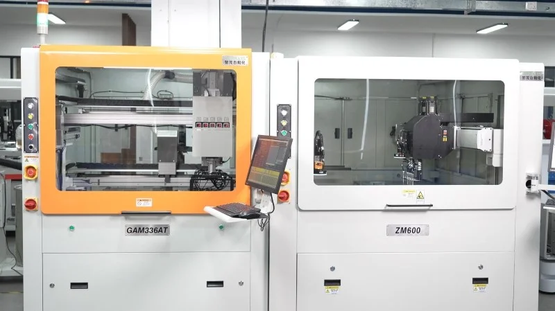
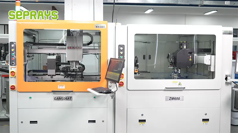
- GAM330AT Fully Automatic PCB Depaneling Machine — Self-feeding operation with automatic sorting — ideal for high-volume automated production lines
- GAM 340AT In-Line Automatic PCB Router Machine — Dual workbench with auto-focus vision camera — maximizes throughput for inline SMT integration
Frequently Asked Questions
I don’t see the article “Networking Scenarios of Inline Routers with Conveyors & Buffer Machines” in the provided context. Let me search for it in the workspace.
I cannot find the article “Networking Scenarios of Inline Routers with Conveyors & Buffer Machines” in the workspace or in the message context.
Could you please provide:
1. The article content, or
2. A file/path to the article, or
3. An attachment if you have the article file
Once you share the article, I’ll generate exactly 3 practical Q&A pairs in the HTML format you specified.
About Seprays
About Seprays Precision Machinery
Founded in 1993, Seprays has over 30 years of expertise in PCB depaneling solutions. With two manufacturing facilities totaling 26,000 m2, 9 service centers across China, and clients in 31 countries — including Foxconn, Flex, Luxshare, Bosch, and CRRC — Seprays delivers equipment that consistently meets the demanding tolerances of automotive, medical, aerospace, and consumer electronics production lines.
Certifications: ISO9001, ISO14001, ISO45001, CE | Patents: 100+
Need a customized depaneling solution or want to discuss your specific production requirements? Our technical team is ready to help.
Contact: jimmy@seprays.com


