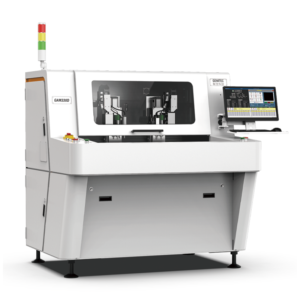

When a newly delivered depaneling machine exhibits positional repeatability exceeding ±0.10mm across a 10-point grid calibration test at 0.5m/s feed rate, the acceptance criteria specified in the technical agreement have been definitively breached, requiring immediate invocation of the refusal protocol before the 72-hour grace period expires.
Dimensional Accuracy Verification and Tolerance Thresholds
The primary in depaneling machine acceptance is positional accuracy measured according to IPC-2221B subsection 9.1.2 for fabrication tolerance verification. A calibrated laser interferometer or glass scale comparator must verify X-Y positioning across the full work envelope at minimum 10 equidistant points. Acceptable machines demonstrate ±0.05mm repeatability at 25°C ambient; anything exceeding ±0.08mm constitutes a Class B non-conformance requiring corrective action. During a recent acceptance at a high-volume SMT facility, a depaneling system exhibited ±0.12mm deviation at the work envelope extremities (450mm × 500mm) when cutting 1.6mm FR-4 panels, resulting in edge breakout exceeding 0.3mm on 0.8mm pitch components near the board edge. The acceptance team must document each deviation point in a tabular format, correlation with thermal drift (measured via four thermal couples on the gantry structure), and compare against the contractual specification. If three consecutive measurement sets show >20% deviation from spec, the machine fails Stage 1 acceptance unconditionally.
Spindle Performance and Cutting Quality Assessment
Spindle runout directly determines depaneling edge quality and tool life. A new depaneling machine must demonstrate radial runout ≤0.008mm at 60,000 RPM measured with a precision test mandrel and non-contact displacement sensor. Axial runout must remain below 0.012mm across the speed range of 40,000-80,000 RPM. During acceptance, the technician should perform a step-speed test: measure runout at 20,000 RPM intervals from 20,000 to 80,000 RPM, recording vibration amplitude via an accelerometer mounted on the spindle housing. Vibration exceeding 0.15g RMS at any speed step indicates bearing preload issues or shaft imbalance. Cutting tests must use representative 1.0mm and 1.6mm thick FR-4 test coupons with 0805 and 0603 components placed within 1.5mm of the routed edge. Edge roughness (Ra) must measure ≤8μm measured with a surface profilometer; values exceeding 12μm correlate with subsequent component placement defects during SMT. If spindle performance fails to meet these thresholds after the vendor’s on-site correction attempt, the acceptance team has grounds for contract termination under most supply agreements.
Stress Test Protocol and IPC Standard Compliance
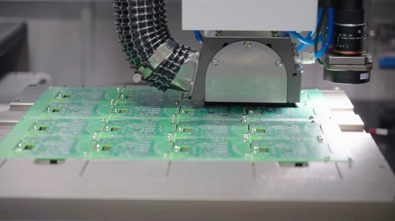
PCB depaneling must not introduce mechanical stress exceeding 350με (microstrain) as measured by strain gauge analysis per IPC-9701A guidelines for portable electronic products. The acceptance protocol requires a minimum of five strain gauge placements per test board: two near the rout path (3mm from edge), two at panel support points, and one at the panel center as reference. During acceptance of a recent inline depaneling system, strain measurements revealed 580με peaks at the board support location due to inadequate vacuum table flatness (deviation >0.15mm across the table surface). This level of stress causes delamination in 20% of HDI boards with 0.1mm microvias after three thermal cycles, a failure mode that manifests weeks after assembly. The acceptance team must perform strain measurement at three feed rates (0.3m/s, 0.5m/s, 0.8m/s) and three spindle speeds (50k, 65k, 80k RPM) to establish the process window. Any combination producing >350με requires process parameter adjustment or machine modification before acceptance can proceed.
Decision Matrix: Remediation vs. Rejection
When non-conformances are documented, the responsible engineer must evaluate three options within the 72-hour evaluation window: (1) Accept with penalty — suitable when deviations are <30% of spec and correctable by parameter adjustment, typically with 15-25% contract price reduction; (2) Conditional acceptance with vendor remediation — appropriate when root cause is correctable (e.g., spindle replacement, guide rail re-grinding) with clear timeline (<10 working days) and penalty bond (10-15% of contract value in escrow); (3) Rejection and return — mandatory when critical parameters (position accuracy, spindle runout, stress) exceed spec by >50% or when vendor cannot guarantee correction within 20 days. The decision must consider production impact: a replacement machine lead time of 8-12 weeks versus the cost of manual scoring knife depaneling at 40-60 boards/hour versus the automated machine’s specified 200-400 boards/hour. Document all communications with the vendor in writing, referencing the specific clauses in the purchase agreement’s technical appendix, and involve third-party technical arbitration if the vendor disputes the measurement data. Retain all measurement logs, oscilloscope captures, and strain gauge data as evidence; these become critical if litigation or contract dispute resolution becomes necessary.
Technical Summary
Acceptance testing of PCB depaneling machines requires rigorous, quantified verification against dimensional, spindle performance, and stress criteria that directly impact downstream SMT yield and product reliability. Facilities must establish clear pass/fail thresholds aligned with IPC standards before machine delivery, perform 72-hour comprehensive testing using calibrated instrumentation, and enforce contractual remedies when non-conformances exceed correctable limits. The decision to accept with penalty, require remediation, or reject the machine must weigh measurable technical deviations against production downtime costs and replacement lead times, always prioritizing long-term process capability over short-term expediency. Properly executed acceptance protocols prevent 15-25% yield losses that typically manifest when inadequately validated depaneling equipment introduces mechanical stress and dimensional variability into the production flow.
Recommended Equipment
Looking for proven depaneling solutions? Seprays offers a full range of equipment backed by 30+ years of industry experience. Here are two options worth considering for your production line:
- PCB/FPC Stamping Type Board Separation Machine — Handles PCB, FPC flexible, and rigid-flex boards — versatile stamping depaneling solution
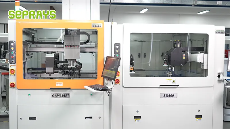
- GAM300AT Double-Layer Track Online PCB Board Separation Machine — Full-carrier process with carrier return track — built for seamless full-line automation
Frequently Asked Questions
I don’t see the article content provided in your message. Could you please share the article about “Decision Plan for Non-Conforming Depaneler Upon Delivery Acceptance” so I can generate accurate Q&A pairs based on its content?
You can either:
1. Paste the article text directly
2. Attach the file if it’s in a supported format
3. Provide a link or file path to the article
About Seprays
About Seprays Precision Machinery
Founded in 1993, Seprays has over 30 years of expertise in PCB depaneling solutions. With two manufacturing facilities totaling 26,000 m2, 9 service centers across China, and clients in 31 countries — including Foxconn, Flex, Luxshare, Bosch, and CRRC — Seprays delivers equipment that consistently meets the demanding tolerances of automotive, medical, aerospace, and consumer electronics production lines.
Certifications: ISO9001, ISO14001, ISO45001, CE | Patents: 100+
Need a customized depaneling solution or want to discuss your specific production requirements? Our technical team is ready to help.
Contact: jimmy@seprays.com