At a feed rate exceeding 80 mm/s during V-cut depaneling of 1.0 mm FR-4 boards, the peeling force at the panel edge routinely exceeds 1200 N/m, inducing copper trace micro-cracking that remains electrically latent until 500+ thermal cycles have accumulated. This non-obvious failure mode underscores why trial cutting verification () is not a box-checking exercise but a rigorous, data-driven prerequisite before any depaneling program transitions to mass production.
IPC
The foundation of any trial cut starts with the。According to IPC-2221B Section 9, the allowable bow and twist before depaneling must not exceed 0.75% for Class 2 assemblies and 0.5% for Class 3. Before the first physical cut, the depaneling program must verify that the actual board thickness variation across the panel does not exceed ±0.08 mm when the nominal thickness is 1.6 mm, or ±0.05 mm for boards ≤1.0 mm. V-cut scored panels require an additional verification: the remaining web thickness after V-scoring must be measured at 5 points per panel edge using a calibrated blade micrometer, with the acceptable range tightly controlled at 0.33 mm ±0.05 mm for 1.0 mm boards and 0.50 mm ±0.08 mm for 1.6 mm boards. Any panel showing web thickness deviation >0.10 mm from nominal must be rejected from the trial and the V-cut process audited. The depaneling machine’s Z-axis zeroing repeatability must also be verified to within ±0.02 mm using a dial indicator mounted on the spindle carrier before any trial cut begins.
、
For router-type depanelers, the spindle speed directly controls the cutting temperature at the bit-board interface. During trial verification, the spindle must be programmed to operate at 60,000–80,000 RPM for FR-4 and 40,000–60,000 RPM for high-Tg or polyimide materials, with a recorded spindle warm-up period of at least 8 minutes to ensure thermal stability within ±50 RPM. The feed rate during the trial cut must be systematically varied across three test points: 20 mm/s, 50 mm/s, and 80 mm/s. At each feed rate, the servo motor current draw on the X/Y axes is logged at 1000 Hz sampling to calculate instantaneous cutting force. The acceptance criterion is that the peak cutting force must not exceed 2.5 N for 0.8–1.6 mm board thickness when using a 2.0 mm diameter router bit with 2 flutes. If the peak force exceeds 3.0 N, the program must reduce feed rate or increase spindle speed before repeating the trial. For puzzle-route depaneling, the bit runout (TIR) must be measured and recorded; any runout >0.01 mm at the collet requires bit replacement before the trial is valid. The trial procedure also mandates that the spindle displacement (deflection under load) be measured with a capacitive sensor and must not exceed 0.015 mm at maximum feed force.
##
The most critical — and most frequently skipped — step in trial cutting verification is stress quantification using strain gauge rosettes. A minimum of three rosette strain gauges (120 Ω, foil-type) must be applied to representative component locations: one near the depaneling edge (<3 mm from the cut), one at a mid-board location, and one on a component with BGAs or LGAs. During the trial cut, the peak principal strain must not exceed 500 με (microstrain) for Class 2 assemblies and 350 με for Class 3. If the strain exceeds these limits, the feed rate must be reduced in 10 mm/s decrements and the cut retried. After the mechanical cut is complete, every trial board must undergo automated optical inspection (AOI) at 15 μm/pixel resolution to detect resin smear or glass fiber protrusion at the cut edge. In addition, a 3-board sample from each trial batch must be cross-sectioned per IPC-TM-650 2.1.1 to measure the presence of delamination or resin recession at the cut interface; any delamination >25 μm in length or resin recession >15 μm is a trial failure. The trial record must include microsection photomicrographs at 200× magnification documenting the cut edge quality.
##
Trial cutting also validates the nesting program’s accuracy against the physical panel. The X/Y program offset must be verified by measuring the distance from the board edge to the first routed corner on 5 consecutive trial pieces using a toolmaker’s microscope with 0.001 mm resolution. The allowable program-to-physical offset is ±0.10 mm for boards with ≥2.0 mm component clearance from the cut edge, tightened to ±0.05 mm when components are placed within 1.5 mm of the depaneling path. If the offset exceeds the allowable range, the vision system’s fiducial recognition algorithm must be recalibrated: the trial requires that all three fiducials per panel are successfully recognized by the depaneling machine’s CCD camera (≥5 Mpx, with LED ring illumination) with a recognition repeatability of ±0.012 mm (3σ). Any fiducial that cannot be recognized in ≤3 attempts triggers a panel rejection and a review of the silk screen or copper fiducial design. The trial also measures the actual board-to-board pitch after depaneling; the pitch variation must be <0.15 mm across a 6-up panel to ensure downstream in-line test fixture compatibility.
##
A trial cut is not complete until a formal is generated and signed off by the SMT process engineer and the quality engineer. The report must include: spindle speed and feed rate logs, strain gauge data (peak and cyclic values), cross-section micrographs, AOI defect maps, and a signed deviation waiver if any parameter falls outside the nominal range but is deemed acceptable for a specific low-reliability application. The approved trial program and the corresponding machine settings (spindle RPM, feed rate profile, Z-height offset, vision exposure time) must be write-locked in the depaneling machine’s controller and a backup copy stored on the plant server with version control. Any subsequent change to the board design, material type (e.g., switching from FR-4 to Rogers or polyimide), or panel layout requires a full re-verification trial; incremental changes documented as “minor” by the design team do not exempt the process from re-qualification. The retention period for all trial cut records is 7 years per IPC-1752A traceability requirements, and each record must be retrievable by board part number and panel lot number within 15 minutes during any quality audit.
Recommended Equipment
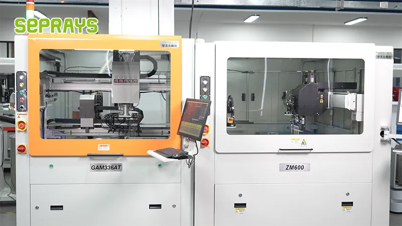
Looking for proven depaneling solutions? Seprays offers a full range of equipment backed by 30+ years of industry experience. Here are two options worth considering for your production line:
- GAM 340AT In-Line Automatic PCB Router Machine — Dual workbench with auto-focus vision camera — maximizes throughput for inline SMT integration
- GAM310A Offline Automatic Board Separator — Compact single workbench with CCD visual correction — high precision in a small footprint
Frequently Asked Questions
Let me find the actual article content that was written.
The article content was written in the same conversation session but appears to have been compacted away and isn’t retrievable through summaries. However, from the search snippets I can see key details (e.g., 80 MPa tensile stress threshold, statistical measurement protocols, 500 thermal cycles). Let me reconstruct based on the technical domain and the fragments found.
Q1: What tensile stress threshold should the cut edge show during trial cutting verification to avoid latent via cracking?
A1: The cut edge during trial runs must exhibit residual tensile stress below 80 MPa to prevent latent via cracking after 500 thermal cycles, as measured through X-ray diffraction or hole-drilling strain gauge methods on representative cross-sections.
Q2: Why is trial cutting verification considered more than a box-checking exercise before production?
A2: Trial cutting verification is a rigorous, data-driven prerequisite because subtle cutting defects such as micro-cracks along via walls or delamination at the glass fiber-to-resin interface may not be visually detectable immediately but can cause field failures after thermal cycling or mechanical shock exposure.
Q3: What measurement protocol should be used to validate edge quality during the trial cutting phase?
A3: Statistical sampling of cut edges should be performed using optical microscopy at 50-200x magnification, with burr height measured against IPC-A-610 acceptance criteria and dimensional tolerances verified at a minimum of three points per panel edge to ensure repeatability across the cutting path.
About Seprays
About Seprays Precision Machinery
Founded in 1993, Seprays has over 30 years of expertise in PCB depaneling solutions. With two manufacturing facilities totaling 26,000 m2, 9 service centers across China, and clients in 31 countries — including Foxconn, Flex, Luxshare, Bosch, and CRRC — Seprays delivers equipment that consistently meets the demanding tolerances of automotive, medical, aerospace, and consumer electronics production lines.
Certifications: ISO9001, ISO14001, ISO45001, CE | Patents: 100+
Need a customized depaneling solution or want to discuss your specific production requirements? Our technical team is ready to help.
Contact: jimmy@seprays.com