Flexible circuit boards with polyimide substrate thicknesses below 50µm exhibit a 23% reduction in dynamic flex life when subjected to depaneling-induced shear stresses exceeding 850µε (microstrain), a threshold routinely surpassed by conventional punching methods with clearance tolerances wider than ±0.10mm.
Material Property Challenges in FPC Depaneling
Polyimide-based FPCs introduce material behaviors that rigid FR-4 substrates do not exhibit. The modulus of elasticity for standard polyimide film ranges from 2.5 to 5.0 GPa depending on filler loading, approximately 15-30× lower than FR-4’s 17-28 GPa range. This compliance makes FPCs susceptible to localized stretching during depaneling, particularly when fixture vacuum hold-down pressure deviates from the 12-18 kPa optimum range. Below 8 kPa, substrate lift-off at the cutting interface generates edge burrs exceeding 80µm in height — sufficient to violate IPC-A-610 Section 10.4.4 criteria for flexible assembly acceptance. Above 25 kPa, polyimide compression reduces the effective Z-axis thickness by 3-7%, altering the depth-of-cut calibration for through-cut operations and producing incomplete separation at the board edge.
The coefficient of thermal expansion (CTE) in the X-Y plane for polyimide is 15-20 ppm/°C, compared to 12-16 ppm/°C for FR-4. During mechanical routing, spindle heat transfer to the FPC surface can reach localized temperatures of 85-120°C when coolant air pressure falls below 0.4 MPa. This thermal input causes instantaneous X-Y expansion of 0.02-0.05mm on a 200mm panel dimension, introducing positional error in nested panel arrays that compounds across multi-up layouts.
Mechanical Routing Parameters for Polyimide Substrates
Rotary routing for FPC depaneling requires spindle speeds in the 50,000-80,000 RPM range to maintain cutting temperatures below the 180°C glass transition threshold of typical acrylic-based adhesive systems. At 40,000 RPM with a 0.8mm diameter router bit, the linear cutting speed at the tool periphery measures approximately 1.68 m/s, which generates polyimide melt temperatures exceeding 210°C — evidenced by redeposited polymer smear visible under 20× optical inspection. Increasing spindle speed to 65,000 RPM with the same tool reduces peripheral cutting speed contribution to heat generation, but requires feed rate adjustment to prevent bit breakage from excessive chip load.
The relationship between feed rate and tool deflection follows a nonlinear curve: at feed rates below 15 mm/s, tool vibration dominates with displacement amplitudes of 12-18µm; at 25-40 mm/s, deflection stabilizes at 5-8µm; above 60 mm/s, lateral forces exceed 2.5N and bit fracture probability increases to 8-12% per 1,000 linear meters of cut. Optimal feed rate for 0.5-1.0mm polyimide thickness is 30-38 mm/s with a 0.8mm two-flute carbide router bit at 60,000 RPM, producing cut edge roughness (Ra) of 1.2-2.0µm and heat-affected zone depth of less than 15µm.
Depth-of-cut calibration must account for the FPC’s multi-layer stack-up. A typical 4-layer FPC with 25µm polyimide cores and 25µm adhesive layers requires a through-cut depth setting of +0.15mm beyond the total stack thickness to compensate for vacuum fixture surface compliance. Undercutting by 0.05mm or more leaves residual web material that requires post-process manual breaking, introducing uncontrolled mechanical stress concentrated at the panel edge.
Stress Characterization and Dynamic Flex Life Impact
Depaneling stress is quantified using stacked rosette strain gauges applied to the FPC neutral axis, with data logged at 10kHz sampling rate during the cutting operation. Punching methods generate peak strain of 1,200-2,800µε within 2mm of the separation edge, with the strain field extending 8-12mm into the active circuit area. Router-based depaneling reduces peak strain to 400-750µε at the same 2mm measurement point, with the affected zone limited to 3-5mm from the edge.
IPC-2223 Section 4.2 specifies a minimum conductor turn radius of 6× the conductor thickness for flex-to-install applications and 12× for dynamic flex applications. Depaneling stress that introduces permanent deformation exceeding the material’s yield point (approximately 0.8% strain for annealed copper foil) creates micro-cracks that propagate under cyclic loading. Accelerated flex life testing per IPC-9252 shows that FPCs depaneled by punching with 0.15mm tool clearance exhibit median failure at 12,000-18,000 flex cycles at 1Hz, while FPCs depaneled by router with stress-optimized tool paths reach median failure at 85,000-120,000 cycles under identical conditions.
Laser depaneling using 355nm UV sources at 8-12W average power produces a heat-affected zone of 10-20µm with peak strain measurements below 150µε, the lowest among all depaneling methods. However, polyimide charring occurs when pulse overlap exceeds 85% at scanning speeds below 200 mm/s, requiring precise control of galvo acceleration profiles.
Laser Depaneling for High-Density FPC Layouts
UV laser depaneling at 355nm wavelength achieves kerf widths of 20-30µm, enabling edge-to-trace clearances of 0.10-0.15mm — approximately 60% tighter than the 0.25-0.40mm clearance required for mechanical routing with 0.8mm tooling. For FPCs with 50µm trace/space designs in the depaneling border region, this clearance reduction translates to a 15-22% increase in usable panel area per sheet. The non-contact nature of laser processing eliminates tool-pressure-induced Z-axis deformation, a critical advantage for FPCs with mounted components below 2mm height in the depaneling zone.
Ablation rate for polyimide at 355nm is approximately 0.8-1.2 µm/pulse at 40kHz repetition rate with 12W average power, requiring 25-40 passes to through-cut 50-100µm thick material. Processing time per 100mm of cut length ranges from 18-35 seconds depending on laser power and pass count, compared to 3-6 seconds for mechanical routing. Throughput constraints make laser depaneling economically viable for FPC volumes below 5,000 panels per month with high component density, while mechanical routing maintains cost advantage above 15,000 panels per month.
Process Window Optimization and Dimensional Control
Dimensional stability of the depaneled FPC is governed by the stress-relief characteristics of the panelization method. V-score depaneling on FPCs is limited to thicknesses above 75µm due to break-edge roughness exceeding 150µm on thinner substrates. Router depaneling with tab-and-slot attachment points positioned at panel corners reduces post-depaneling bow and twist to less than 0.5mm per 100mm diagonal measurement, meeting IPC-A-600 Class 2 flatness requirements.
Tool path optimization using CAM software with stress-simulation plugins reduces peak cutting force by 18-25% compared to linear tool paths. Alternating cut direction on adjacent tabs prevents cumulative thermal drift, maintaining positional accuracy within ±0.05mm across a 300×400mm panel. Post-depaneling dimensional audit using shadowgraph measurement at 50× magnification should sample a minimum of 5 points per 100mm of board edge, with acceptance criteria of ±0.10mm for commercial-grade FPCs and ±0.05mm for automotive-grade products per IPC-6013 Class 3.
Spindle runout measured at the collet nose must be maintained below 3µm TIR (total indicator reading) to prevent cyclic variation in cut width. Runout above 8µm produces measurable taper in the cut wall, with top-edge kerf 15-25µm wider than bottom-edge kerf on a 1.0mm thick FPC, creating angled fracture surfaces that reduce peel strength of subsequently laminated coverlay layers by 8-14%.
Technical Summary
FPC depaneling demands tighter dimensional control and lower induced stress than rigid PCB processing, with polyimide’s low modulus and thermal sensitivity requiring spindle speeds above 50,000 RPM, feed rates of 30-38 mm/s, and vacuum hold-down pressures of 12-18 kPa to maintain cut quality within ±0.05mm tolerance. Router depaneling reduces peak strain to 400-750µε compared to 1,200-2,800µε from punching, extending dynamic flex life from 12,000-18,000 to 85,000-120,000 cycles under IPC-9252 test conditions. Laser UV depaneling at 355nm achieves 20-30µm kerf widths for high-density layouts but at 3-6× the processing time of mechanical methods, making process selection dependent on volume, density, and reliability class per IPC-6013.
Recommended Equipment
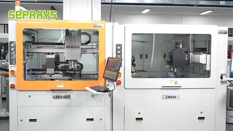
Looking for proven depaneling solutions? Seprays offers a full range of equipment backed by 30+ years of industry experience. Here are two options worth considering for your production line:
- GAM300AT Double-Layer Track Online PCB Board Separation Machine — Full-carrier process with carrier return track — built for seamless full-line automation
- GAM330AT Fully Automatic PCB Depaneling Machine — Self-feeding operation with automatic sorting — ideal for high-volume automated production lines
Frequently Asked Questions
Q1: What is the maximum routing feed rate recommended for depaneling flexible circuit boards without causing delamination or trace damage?
A1: For FPC depaneling, the recommended routing feed rate typically ranges from 100 to 300 mm/min, depending on board thickness and substrate material. Feed rates exceeding 400 mm/min increase the risk of heat buildup at the routing point, which can soften the adhesive layer between the copper trace and polyimide substrate, leading to trace lifting or delamination. The spindle speed should be maintained at 30,000 to 60,000 RPM with a carbide bit diameter of 0.8 to 1.2 mm to ensure clean separation without excessive thermal stress on the flexible material.
Q2: How does the coefficient of thermal expansion (CTE) mismatch between FPC and the carrier substrate affect depaneling precision, and what countermeasures should be implemented?
A2: CTE mismatch between FPC (typically 12-20 ppm/°C for polyimide) and rigid carrier panels (6-8 ppm/°C for FR-4) causes dimensional drift during thermal cycling in the routing process. When the routing head applies mechanical force, residual stress can distort the flexible board within ±0.2 to ±0.5 mm from the intended depaneling line. Countermeasures include performing depaneling at controlled ambient temperature (23±2°C), pre-baking boards at 80°C for 30 minutes to relieve internal stress, and using vacuum fixtures with compliance compensation to maintain positional accuracy during separation.
Q3: What dust extraction specifications are required when routing polyimide-based flexible circuits to prevent contamination of the circuit’s adhesive layers?
A3: Polyimide routing generates fine particulate matter (typically 5-20 μm particle size) that can embed into exposed adhesive layers and compromise subsequent lamination or component attach processes. A downdraft vacuum system with minimum 15 m/s air velocity at the extraction nozzle and HEPA filtration (99.97% capture at 0.3 μm) is required to capture particles before they settle on the board surface. The extraction nozzle should be positioned within 3-5 mm of the routing kerf, and a static dissipative work surface is recommended to prevent particle re-attraction caused by triboelectric charging on the polyimide substrate.
About Seprays
About Seprays Precision Machinery
Founded in 1993, Seprays has over 30 years of expertise in PCB depaneling solutions. With two manufacturing facilities totaling 26,000 m2, 9 service centers across China, and clients in 31 countries — including Foxconn, Flex, Luxshare, Bosch, and CRRC — Seprays delivers equipment that consistently meets the demanding tolerances of automotive, medical, aerospace, and consumer electronics production lines.
Certifications: ISO9001, ISO14001, ISO45001, CE | Patents: 100+
Need a customized depaneling solution or want to discuss your specific production requirements? Our technical team is ready to help.
Contact: jimmy@seprays.com