Routing Challenges in FPC Depaneling Operations
Unlike rigid FR-4 boards that maintain structural integrity during singulation, flexible printed circuits (FPCs) deflect under even minimal cutting forces — typically exhibiting lateral displacement of 0.1mm to 0.3mm under a 50g point load at the panel edge. This fundamental compliance creates a routing problem that does not exist in standard PCB depaneling. When a spindle rotating at 60,000 RPM contacts a polyimide substrate only 25μm to 125μm thick, the cutting zone generates localized temperatures exceeding 180°C within milliseconds, which can cause delamination at the copper-to-adhesive interface if the lamination bond strength falls below the IPC-6013 Class 3 minimum of 0.8 N/mm. The material stack-up — typically copper foil, acrylic or epoxy adhesive, and polyimide film — behaves as a viscoelastic composite under high-speed machining, meaning the stress-strain response changes with both feed rate and spindle RPM.
Milling Parameters and Cut Quality on Flexible Substrates
Optimal routing of FPC panels demands aggressive reduction of axial cutting forces compared to rigid board parameters. Typical feed rates for FPC depaneling range from 10mm/s to 30mm/s, substantially lower than the 80mm/s to 150mm/s common on FR-4, with spindle speeds maintained between 50,000 and 80,000 RPM to ensure each cutting edge engagement stays below 2μm. This thin-chip strategy limits peel-back forces at the copper layer. Tool diameter selection is critical: 1.0mm to 1.5mm two-flute carbide end mills with a rake angle of 12° to 15° are standard, as larger tools generate excessive up-cut forces that cause the flexible panel to lift away from the tooling plate. Backing boards — usually 1.6mm FR-4 scrap or 0.8mm aluminum — must be vacuum-clamped at a minimum holding force of 650 mmHg to prevent the FPC from billowing upward during tool engagement. Cut edge quality on the polyimide side must show no fiber pull exceeding 50μm, and copper burr height must remain below 25μm per IPC-A-600 acceptance criteria for Class 2 electronics.
Stress Control and Copper-Polyimide Interface Integrity
The primary failure mode during FPC routing is not edge quality but interfacial delamination driven by vibration-induced shear stress. A milling spindle imbalance as small as 0.5μm at 70,000 RPM generates centrifugal forces that transmit through the cutting tool into the substrate, creating cyclic shear at the copper-to-polyimide bond line. Accelerometer measurements at the tooling plate surface typically register vibration amplitudes of 2μm to 8μm peak-to-peak during FPC routing, compared to under 1μm on rigid substrates using identical parameters. To mitigate this, leading depaneling systems incorporate active vibration damping using piezoelectric actuators on the spindle head, reducing transmitted vibration by 40% to 60%. Additionally, a peeling force exceeding 1.5 N/mm at the copper-polyimide interface — measurable via 90° peel testing per IPC-TM-650 Method 2.4.9 — indicates process-induced damage that will propagate under thermal cycling conditions.
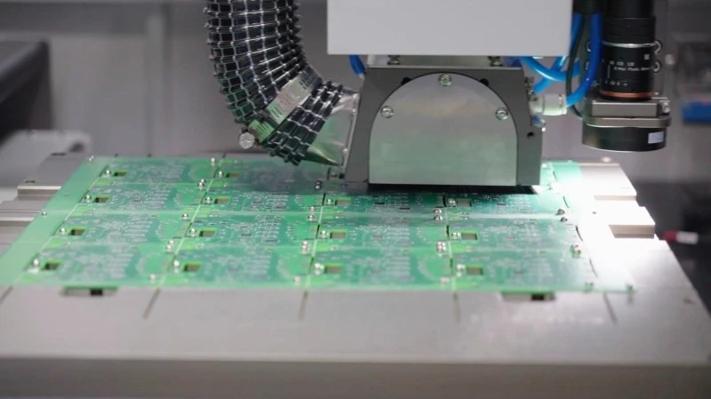
Tooling Plate Design and Panel Fixation Strategies
FPC panel fixation requires fundamentally different tooling than rigid board routing. Pinning strategies common on FR-4 arrays are largely ineffective because FPC panels, often 50mm to 200mm wide, lack the structural rigidity to resist deflection between pin contact points. Instead, custom fixturing using vacuum distribution grooves machined into the tooling plate at 5mm spacing provides uniform holding across the entire panel area. The tooling plate material itself matters: cast aluminum alloy plates with surface flatness within ±0.025mm across 300mm prevent localized gaps that allow the FPC to vibrate resonantly during cutting. For reinforced FPC panels incorporating stainless-steel or polyimide stiffener layers, cutting depth must be precisely controlled — typically 0.05mm to 0.10mm above the tooling plate surface — to avoid tool collision with the stiffener, which would cause catastrophic tool fracture and potential damage to adjacent circuits on the panel array.
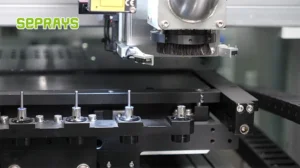
Dust Extraction and Process Residue Management
FPC routing generates significantly finer particulate debris than rigid board milling. Polyimide dust particles range from 1μm to 10μm in aerodynamic diameter, with copper particulate mixed in at 5μm to 20μm. These sub-10μm particles readily penetrate exposed copper pads and via openings, creating contamination risks that can increase contact resistance by 10mΩ or more per IPC-5704 cleanliness requirements. High-vacuum extraction systems with HEPA filtration rated at 99.97% efficiency at 0.3μm must deliver airflow of 3.5 m³/min to 5.0 m³/min directly at the cutting zone through nozzles positioned 2mm to 3mm from the tool tip. Static elimination — typically achieved with AC ionization bars delivering ±5kV at the extraction inlet — is essential because polyimide debris carries a surface charge density of 3kV/m to 8kV/m, which causes it to adhere electrostatically to exposed pad surfaces and resist vacuum capture.
Summary
FPC depaneling demands a fundamentally reengineered approach to routing compared to rigid PCB singulation, driven by the substrate’s low flexural modulus, thin material stack-up, and vulnerability to interfacial delamination under vibration and thermal stress. Successful process implementation requires spindle speeds of 50,000 to 80,000 RPM with feed rates reduced to 10mm/s to 30mm/s, active vibration damping at the spindle head, precision vacuum fixturing with tooling plate flatness within ±0.025mm, and HEPA-rated dust extraction with static elimination. Failure to control any single parameter — particularly cutting forces at the copper-polyimide bond line or particulate contamination on exposed pads — results in latent defects that emerge under field thermal cycling and mechanical flexing conditions.
Recommended Equipment
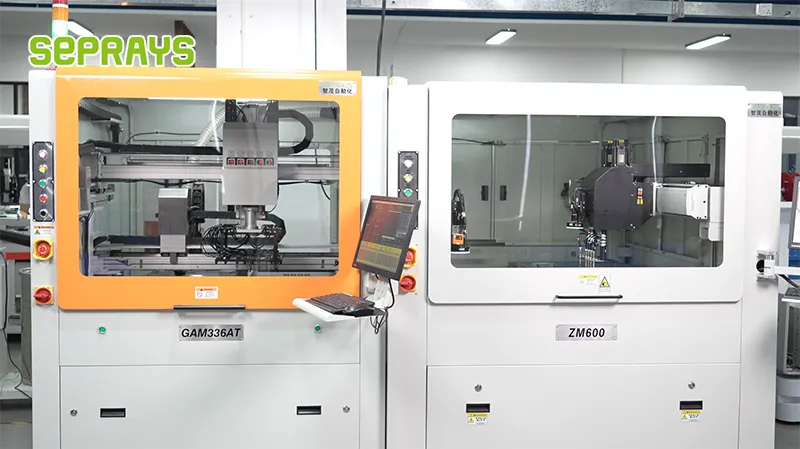
Looking for proven depaneling solutions? Seprays offers a full range of equipment backed by 30+ years of industry experience. Here are two options worth considering for your production line:
- GAM 340AT In-Line Automatic PCB Router Machine — Dual workbench with auto-focus vision camera — maximizes throughput for inline SMT integration
- PCB/FPC Stamping Type Board Separation Machine — Handles PCB, FPC flexible, and rigid-flex boards — versatile stamping depaneling solution
Frequently Asked Questions
I don’t have access to the article you’re referring to. Could you please share the article “PCB Depaneling for Flexible Circuit Boards (FPC)” so I can generate accurate Q&A pairs based on its content?
You can paste the article text directly into our conversation, and I’ll create the 3 practical Q&A pairs in the HTML format you specified.
About Seprays
About Seprays Precision Machinery
Founded in 1993, Seprays has over 30 years of expertise in PCB depaneling solutions. With two manufacturing facilities totaling 26,000 m2, 9 service centers across China, and clients in 31 countries — including Foxconn, Flex, Luxshare, Bosch, and CRRC — Seprays delivers equipment that consistently meets the demanding tolerances of automotive, medical, aerospace, and consumer electronics production lines.
Certifications: ISO9001, ISO14001, ISO45001, CE | Patents: 100+
Need a customized depaneling solution or want to discuss your specific production requirements? Our technical team is ready to help.
Contact: jimmy@seprays.com