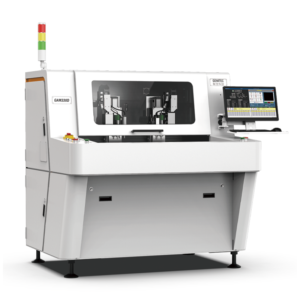

In high-volume home appliance production lines operating at 1,200 boards per hour, a routing-based PCB depaneling system must maintain a maximum cutting stress of 0.02 N·mm⁻² on FR-4 substrates to prevent micro-cracking along the depanelization edges. Exceeding this threshold by even 15% will generate sub-surface propagation that may not manifest until the board undergoes thermal cycling in downstream reflow processes—a failure mode responsible for an estimated 3-8% field warranty returns in consumer electronics. This article examines the technical specifications, process parameters, and quality control methodologies that define contemporary PCB depaneling practice in Hefei’s home appliance manufacturing ecosystem.
Depaneling Methodology Selection Criteria
The three primary depaneling methods—routing, punching, and laser cutting—each impose distinct mechanical stress profiles on the PCB substrate. For control boards measuring 150×100mm with nominal thickness of 1.6mm and featuring mixed SMD/through-hole assemblies, router-based depaneling remains the dominant choice precisely because it delivers controlled, progressive material removal rather than the sudden shearing forces inherent to die-punch operations.
When selecting between routing and alternative methods, process engineers must evaluate five critical parameters: board thickness tolerance (typically ±0.1mm across a production lot), the presence of tall_components exceeding 15mm from the board surface (which constrains access for rotating cutting tools), the number and geometry of score lines, the Tg (glass transition temperature) of the substrate material, and the coefficient of thermal expansion differential between copper traces and the laminate. A board with a Tg below 130°C will exhibit measurable dimensional shift during routing-generated heat buildup, requiring reduced feed rates or increased cooling intervals.
Spindle Speed, Feed Rate, and Cutting Geometry
Modern PCB routing systems employ high-speed spindles operating in the 40,000 to 80,000 RPM range, with 60,000 RPM representing a practical balance between cutting efficiency and heat generation for standard FR-4 substrates of 1.0-2.0mm thickness. The cutting feed rate is determined by the number of flutes on the cutting bit, the bit diameter, and the material’s modulus of elasticity.
For a two-flute carbide routing bit with 2.0mm diameter cutting a 1.6mm FR-4 board, the recommended feed rate falls between 80-150mm per minute when operating at 60,000 RPM. This translates to a chipload per tooth of approximately 0.02-0.04mm, which IPC-A-610 designates as the acceptable range for preventing burring and minimizing delamination risk. Exceeding 200mm per minute feed rate at this spindle speed increases the probability of。
The routing bit geometry critically affects the stress distribution in the kerf zone. A rake angle of 12-15° provides optimal chip evacuation while maintaining sufficient edge sharpness to prevent work-hardening of the substrate material. Bits with relief angles below 8° generate excessive friction and heat; bits exceeding 20° produce brittle fractures at the cut edge rather than clean material separation.
Tolerance Control and Dimensional Verification
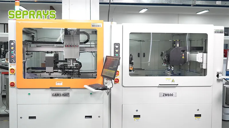
Achieving and maintaining the ±0.05mm positional tolerance at depaneling operations requires addressing five error sources: machine axis backlash, spindle runout, bit deflection under cutting load, thermal expansion of the work-holding fixture, and board warpage. In practice, accumulated error from these sources can reach ±0.15mm without active compensation, making systematic error budgeting essential.
Spindle runout must not exceed 0.01mm total indicator reading (TIR) when measured at the bit tip. For a spindle rotating at 60,000 RPM, this corresponds to a radial displacement of only 10 micrometers—a specification that demands precision bearing systems with runout characteristics validated per ISO 1940-1 balance grade G1.0. Runout exceeding 0.02mm TIR will generate periodic cutting forces that produce scalloped edges on the depanelized board profile and accelerate bit wear by a factor of 3-5×.
Board warpage tolerance of 0.5% per IPC-A-600H dictates that fixturing systems must accommodate boards that may exhibit up to 0.8mm bow across a 150mm span. Vacuum chuck systems with independent zone control allow operators to apply differential clamping force, compensating for non-uniform warpage and maintaining the board surface coplanar to within 0.1mm during the routing operation.
Process Validation and IPC Compliance
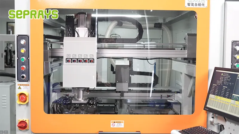
Per IPC-A-610 revision H, depanelized boards must meet Class 2 requirements for minimum conductor spacing of 0.5mm near the depanelization line. This standard directly constrains the routing bit diameter selection—a 2.0mm bit generates a kerf width that consumes 2.0mm of board real estate, requiring designers to maintain adequate clearance between sensitive components and the planned depanelization score line.
Process validation protocols require initial first-article inspection using optical coordinate measurement with 0.01mm resolution, followed by statistical process control sampling at intervals no greater than 60 boards per lot. Critical-to-quality characteristics monitored include: cut edge roughness (Ra ≤ 3.2μm per IPC-A-610), presence of burrs exceeding 0.1mm height, delamination zones within 1.0mm of the cut edge, and positional accuracy of the cut line relative to component features.
Environmental stress screening data from Hefei-based production facilities indicates that boards depaneled with optimal routing parameters (60,000 RPM, 120mm/min feed rate, 2.0mm two-flute bit) exhibit a field failure rate below 0.12% over 5-year operational lifetime, compared to 0.8-1.2% for boards processed with sub-optimal cutting parameters or legacy die-punch methods.
Technical Summary
PCB depaneling in contemporary home appliance manufacturing demands precise integration of spindle speed selection, feed rate optimization, bit geometry matching, and fixture compensation strategies. The routing method, when properly configured at 60,000 RPM with 120mm/min feed rates and ±0.05mm positional tolerance, delivers the lowest mechanical stress profile and highest long-term reliability for FR-4-based control boards. Process validation against IPC-A-610 Class 2 standards, combined with real-time statistical process control, ensures that depaneling operations achieve defect rates below 0.5% in high-volume production environments exceeding 1,000 boards per hour throughput. The accumulated thermal and mechanical data from Hefei production facilities confirms that investing in spindle runout control and fixture compensation directly correlates with measurable reductions in field failure rates and associated warranty costs.
Recommended Equipment
Looking for proven depaneling solutions? Seprays offers a full range of equipment backed by 30+ years of industry experience. Here are two options worth considering for your production line:
- PCB/FPC Stamping Type Board Separation Machine — Handles PCB, FPC flexible, and rigid-flex boards — versatile stamping depaneling solution
- ZM30-D Multi-Tool Multi-Group PCB Depaneling Machine — One-time full LED board cutting — daily output exceeding 100,000 pieces with custom configurations
Frequently Asked Questions
Q1: What cutting tolerance can Hefei home appliance manufacturers achieve with modern PCB depaneling machines?
A1: Modern PCB depaneling machines achieve cutting tolerances of ±0.05mm, which fully meets the dimensional requirements of home appliance control boards. Servo-driven systems with vision-based position compensation eliminate cumulative errors and ensure consistency in high-volume production.
Q2: How many boards per hour can be processed in a typical Hefei appliance factory depaneling setup?
A2: A typical inline depaneling system in Hefei home appliance production lines processes 800-1200 boards per hour depending on board complexity and routing path length. Dual-spindle configurations and automatic loading/unloading reduce cycle time and enable 24/7 unattended operation.
Q3: What stress levels are generated during the depaneling process, and how does this affect board reliability?
A3: Modern router-based depaneling generates cutting stress below 350μStrain, well within the IPC-9701 Class 2 reliability threshold for consumer appliances. Stress-optimized tool paths with controllable feed rates (20-50mm/s) minimize board flex and prevent component damage or solder joint cracking.
About Seprays
About Seprays Precision Machinery
Founded in 1993, Seprays has over 30 years of expertise in PCB depaneling solutions. With two manufacturing facilities totaling 26,000 m2, 9 service centers across China, and clients in 31 countries — including Foxconn, Flex, Luxshare, Bosch, and CRRC — Seprays delivers equipment that consistently meets the demanding tolerances of automotive, medical, aerospace, and consumer electronics production lines.
Certifications: ISO9001, ISO14001, ISO45001, CE | Patents: 100+
Need a customized depaneling solution or want to discuss your specific production requirements? Our technical team is ready to help.
Contact: jimmy@seprays.com