Table of Contents
- 1. Spindle Rotation and Right-Cutting Principle
- 2. Left-Hand Router Bits: Downward Chip Evacuation
- 3. Right-Hand Router Bits: Upward Chip Challenges
- 4. Pocket Milling vs. Contour Milling Strategies
- 5. Dust Management Through Tool Path Direction
- 6. Milling Sequence Optimization Principles
- 7. Fiducial Point Selection for Precision
- 8. Fixture Design Methodology
- 9. PCB Backside Dust Control Solutions
- 10. Preventing Board Flexing Effect
- 11. Extending Spindle Bearing Life
- 12. Troubleshooting Frequent Bit Breakage
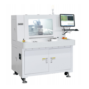
Optimizing your PCB router machine operations requires understanding critical technical parameters and design strategies. This comprehensive guide reveals 12 professional techniques to maximize depaneling quality, minimize downtime, and extend equipment lifespan.
1. Spindle Rotation and Right-Cutting Principle
Most PCB router machines feature right-rotating spindles, creating a “right-cutting” characteristic where the cutting edge engages material from the workpiece’s right side. This standardized design reduces setup errors and ensures operational stability.
2. Left-Hand Router Bits: Downward Chip Evacuation
Identification & Characteristics
Left-hand bits have chip flutes ascending from lower-right to upper-left orientation.
Operational Advantages
- Downward cutting force prevents lifting PCBs
- Simplified bottom-only fixturing requirements
- Compatible with bottom-dust extraction systems
Key Challenge
PCB backside dust accumulation requires precision fixture solutions (see Section 9).
3. Right-Hand Router Bits: Upward Chip Challenges
Identification & Characteristics
Right-hand bits feature chip flutes ascending from lower-left to upper-right.
Application Considerations
- Requires top-dust extraction for surface cleanliness
- Upward cutting force necessitates dual-side fixturing
- Industry preference: CNC machines favor right-hand bits, while PCB router machines typically use left-hand for simplified fixturing
4. Pocket Milling vs. Contour Milling Strategies
| Milling Mode | Material Removal Area | Typical Application |
|---|---|---|
| Pocket Milling | Inside closed path | Separating sub-panels within array |
| Contour Milling | Outside closed path | Separating entire PCB from rails/breakaway tabs |
5. Dust Management Through Tool Path Direction
Chips always discharge on the right side of the tool path direction. Correct routing is essential:
- Pocket milling: Clockwise direction → Dust evacuates inward
- Contour milling: Counter-clockwise direction → Dust evacuates outward
Incorrect direction causes PCB contamination, electrical shorts, and reliability failures.
6. Milling Sequence Optimization Principles
- Maintain panel integrity: Keep uncut subpanels connected to rails
- Short-edge termination: Finish cuts on shortest boundaries near fixtures
- Rail-last processing: Cut rail-connected panels last in sequence
7. Fiducial Point Selection for Precision
Select fiducials at diagonal corners of PCB rails:
- Prioritize points near fixture locating pins
- Position secondary fiducial near starting cut point
This ensures geometric stability even after machining interruptions.
8. Fixture Design Methodology
Precision fixturing improves depaneling quality by 30+%. Follow this 4-step process:
- Map PCB contours and potential locating points
- Design tool paths considering direction and sequence
- Select optimal fiducial points
- Finalize locating pin/clamping positions
9. PCB Backside Dust Control Solutions
Combat dust accumulation in downward-chip systems:
- Airflow optimization: Minimize fixture openings + seal unnecessary gaps
- Slot design: Width = Bit diameter + ½ PCB thickness (e.g., 1.5mm bit → 2.0mm slot)
- Chip formation control: Reduce RPM (40k→25k) or use new bits for coarser chips
- Vacuum port design: Customize using 3D scans/Gerber data for minimal clearance
10. Preventing Board Flexing Effect
Counteract panel separation at cut endings:
- Increase locating pin quantity and distribution
- Position final cuts in non-critical areas
- Implement 0.1mm re-cut at path endpoints
11. Extending Spindle Bearing Life
FR4 Material Bit Life
| Bit Diameter | Cutting Length | Working Segments (1.4mm PCB) |
|---|---|---|
| 1.0mm | 10 meters | 4-5 segments |
| 1.5mm | 15 meters | 4-5 segments |
Bearing Preservation Techniques
- High RPM + low feed rate (e.g., 25,000 RPM at 8mm/s)
- Strict bit replacement schedule (dull bits increase radial force by 50%)
12. Troubleshooting Frequent Bit Breakage
| Symptom | Primary Cause | Solution |
|---|---|---|
| Consistent breakage | Excessive tool wear | Replace bits per standard lifespan |
| Location-specific breakage | Inadequate fixture support | Add local locating pins |
| Breakage on thick PCBs | Radial force overload | Reduce feed rate by 30% |
Optimization Results Summary
Implementing these PCB router machine techniques delivers measurable benefits:
- ✓ 40% longer tool life
- ✓ 90% reduction in dust contamination
- ✓ ±0.05mm depaneling precision
- ✓ 30% reduction in fixture-related defects
Continuous optimization of cutting parameters and fixturing transforms depaneling into a highly controlled, reliable manufacturing process.


