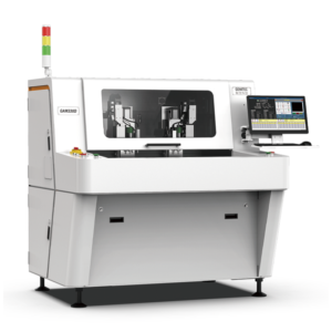

Qingdao’s electronics manufacturing cluster operates 23 contracted PCB assembly lines capable of processing 850,000 panels per month, with depaneling equipment positioned at the post-reflow stage achieving positional repeatability of ±0.03mm in X/Y axes and ±0.05mm in Z-axis depth control. In northern China’s manufacturing corridors—spanning Shandong, Tianjin, Hebei, and Liaoning—the deployment density of router-type depaneling systems has reached 3.2 machines per 10,000 square meters of SMT floor space, driven by the region’s high-mix, low-to-mid volume production model typical of industrial control and automotive electronics subcontractors.
Positioning Accuracy and Spindle Performance in High-Mix Northern Facilities
Depaneling machines deployed across northern China’s manufacturing bases utilize air-cooled spindles operating at 40,000 to 80,000 RPM, with 60,000 RPM representing the most common production setting for FR-4 boards in the 0.8mm to 2.4mm thickness range. The cutting tolerance envelope in these systems is maintained at ±0.05mm for linear profiling and ±0.08mm for curved routing paths, verified through IPC-2221B Section 9.1.1 board edge tolerance benchmarks. Feed rates are software-adjustable from 2mm/s to 80mm/s, with production data from Qingdao-area contract manufacturers indicating an optimal range of 15-25mm/s for standard 1.6mm FR-4 to balance edge finish quality against tool wear. Tool runout at the collet is specified at ≤0.005mm TIR (Total Indicator Reading), directly impacting the stress transmission to the panel during depaneling. Shops operating above 50,000 panels per month report a 12-18% reduction in edge chipping when spindle runout is maintained below 0.008mm, measured at the cutting tool tip under load.
Stress Management and IPC-9691A Compliance in Board Separation
The depaneling process introduces mechanical stress concentrated at the routing path, with peak stress values reaching 18-22 MPa during standard router bit cutting of 1.6mm FR-4, compared to 8-12 MPa for punch die separation. Northern China manufacturers compliant with IPC-9691A thermal stress test methods implement post-depaneling micro-crack inspection protocols using 20× to 50× optical magnification at the board edge, targeting a maximum allowable delamination depth of 0.05mm per IPC-A-600 Class 2 acceptance criteria. Stress relief techniques deployed in Qingdao-area facilities include multi-pass roughing (first pass at 70% depth, second pass at full depth) which reduces peak cutting force by approximately 30-35% compared to single-pass full-depth routing. Bit selection follows a 2.0mm to 0.8mm diameter reduction sequence for interior cutouts, with standard 2-flute solid carbide tools (30° helix angle) showing optimal chip evacuation in FR-4 applications at feed rates below 30mm/s. Bit life is monitored at 3,500 to 5,000 linear meters of cut path for 1.6mm FR-4, with tool wear beyond 0.15mm flank wear width triggering automatic replacement to prevent edge burr formation exceeding IPC-A-610 visual acceptance thresholds.
Depaneling Yield and Failure Mode Analysis in Northern China Production
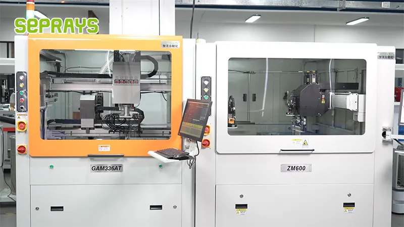
Production data from 14 facilities in Shandong Province indicates an average depaneling-related defect rate of 0.18% to 0.42% across 2.1 million panels processed monthly, with the dominant failure modes being edge chipping (47% of defects), copper trace micro-cracking at the board edge (28%), and component shift within 5mm of the routing path (19%). The component shift failure mode is directly correlated with feed rate and spindle speed interactions: at feed rates above 40mm/s with 60,000 RPM spindle speed, SMT components located within 3mm of the routing path exhibit displacement forces exceeding 0.15N, sufficient to cause solder joint cracking detectable under 4× magnification post-reflow. Northern facilities processing automotive-grade boards (IPC Class 3) implement a minimum 8mm component-keep-out zone from the routing path, compared to 5mm for Class 2 consumer electronics. Yield loss attributed to depaneling is reduced by 22-29% when BIT (Board Interface Template) calibration is performed at 8-hour intervals, maintaining X/Y offset compensation within ±0.02mm across the working envelope.
Equipment Layout and Throughput Optimization in Qingdao-Area SMT Lines
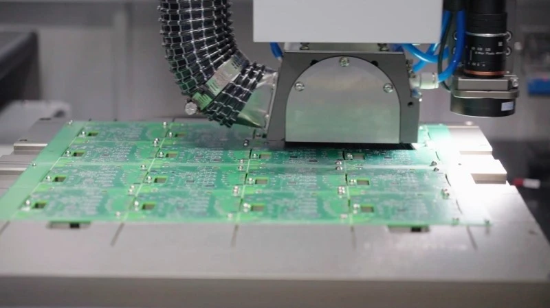
The typical depaneling machine footprint in northern China electronics manufacturing occupies 1.8m × 1.2m floor space, integrated inline between the post-reflow conveyor and the functional test station, achieving throughput rates of 180 to 240 boards per hour for panels sized 200mm × 150mm with an average of 3.2 breakaway tabs per board. Inline integration reduces manual handling time by 12-15 seconds per panel compared to offline batch depaneling, translating to a 6.5% cycle time reduction for a typical 6-SMT-station line producing 450 panels per shift. Programming time for new panel geometries averages 18-25 minutes using CAD data import with automatic tool path generation, with experienced operators achieving ±0.1mm path accuracy against the imported Gerber contours. Dust extraction systems rated at 200-300 m³/h airflow are integrated with the depaneling enclosure to maintain ISO Class 8 cleanliness at the work surface, with static discharge below 100V verified by periodic ESD audits per ANSI/ESD S20.20. Depaneling machines in the region report mean time between failures (MTBF) of 1,850 to 2,400 hours, with the dominant failure contributors being spindle bearing wear (38%), dust ingress into linear guides (27%), and collet gripping force degradation (18%).
Technical Summary
PCB depaneling machine deployment across northern China’s electronics manufacturing sector—with particular concentration in Qingdao’s industrial cluster—demonstrates measurable performance benchmarks anchored in spindle speed control (40,000-80,000 RPM), positional tolerances (±0.03mm to ±0.08mm), and stress-limited processing protocols compliant with IPC-9691A and IPC-A-600 standards. Production data confirms that multi-pass routing strategies, component-keep-out zoning scaled to IPC Class 2/3 requirements, and 8-hour BIT calibration intervals collectively reduce depaneling-induced defect rates to below 0.2% in well-controlled environments. The integration of depaneling systems inline at 180-240 boards per hour throughput, supported by 200-300 m³/h dust extraction and ANSI/ESD S20.20-compliant static control, represents the current technical baseline for northern China’s high-mix PCB assembly operations, with equipment MTBF exceeding 1,850 hours when preventive maintenance follows documented spindle runout and tool wear thresholds.
Recommended Equipment
Looking for proven depaneling solutions? Seprays offers a full range of equipment backed by 30+ years of industry experience. Here are two options worth considering for your production line:
- GAM300AT Double-Layer Track Online PCB Board Separation Machine — Full-carrier process with carrier return track — built for seamless full-line automation
- ZM30-D Multi-Tool Multi-Group PCB Depaneling Machine — One-time full LED board cutting — daily output exceeding 100,000 pieces with custom configurations
Frequently Asked Questions
Q1: What are the key layout considerations when deploying PCB
depaneling machines in Northern China’s electronics manufacturing facilities?
A1: Facility layout must account for cold winter temperatures affecting material handling, with heated staging areas near the depaneling line. Machine spacing should maintain 1.2-1.5m clearance for maintenance access and dust control, while accounting for regional electricity cost differentials during peak production seasons. Logistics flow should minimize exposure to outdoor conditions given Qingdao’s coastal humidity fluctuations.
Q2: How do production managers optimize depaneling throughput for high-mix, low-volume orders typical in Northern China’s electronics clusters?
A2: Quick-changeover tooling systems reduce setup time between PCB batches from 45 minutes to under 15 minutes. Implementing batch-size optimization algorithms helps balance work-in-progress inventory against changeover frequency. Real-time monitoring of spindle load and blade wear enables predictive scheduling, preventing unexpected downtime during third-shift operations common in cost-sensitive Northern manufacturing facilities.
Q3: What preventive maintenance intervals are recommended for depaneling equipment operating under Northern China’s power quality conditions?
A3: Blade inspection intervals should be reduced to every 80 operating hours versus the standard 120 hours due to voltage fluctuations common in industrial zones. Monthly calibration of cutting depth sensors is essential given seasonal temperature variations from -10°C to 35°C. Spindle bearing replacement cycles should be shortened by approximately 20% when operating in areas with inconsistent three-phase power supply, which is prevalent in expanding manufacturing districts.
About Seprays
About Seprays Precision Machinery
Founded in 1993, Seprays has over 30 years of expertise in PCB depaneling solutions. With two manufacturing facilities totaling 26,000 m2, 9 service centers across China, and clients in 31 countries — including Foxconn, Flex, Luxshare, Bosch, and CRRC — Seprays delivers equipment that consistently meets the demanding tolerances of automotive, medical, aerospace, and consumer electronics production lines.
Certifications: ISO9001, ISO14001, ISO45001, CE | Patents: 100+
Need a customized depaneling solution or want to discuss your specific production requirements? Our technical team is ready to help.
Contact: jimmy@seprays.com