During high-volume SMT production, boards emerge from the reflow oven in panel arrays — singular units connected by tab-cut or V-score bridges. These arrays simplify handling and reduce placement errors during assembly, but before the board reaches its final enclosure, each individual unit must be separated with micron-level precision. A board stressed beyond 500 microstrain during separation will develop microcracks in the copper traces near the depaneling route — failures that may not manifest until field operation, making them among the most costly and invisible defects in electronics manufacturing.
The V-Score Mechanism
The most common depaneling method uses a vertical saw or knife blade that penetrates the board along aV. A V-score removes approximately one-third of the board thickness, leaving a controlled hinge of material. The separation then occurs through a controlled break-away force applied by push fingers or aweep blade. The critical parameter here is the remaining gauge thickness — maintaining 0.30–0.40 mm of uncut material after scoring. If the score depth deviates by more than ±0.05 mm from the target, the break force becomes either too high (causing board flexure cracks) or too low (producing unfinished tabs). Typical spindle speeds for V-scoring range from 20,000 to 30,000 RPM, with feed rates of 100–300 mm/s depending on substrate thickness and material composition. The blade itself is typically a resin-bonded diamond disc with a concentration of 45–55 carats per hundred grams, running wet to suppress thermal expansion during cutting.
Router-Type Separation
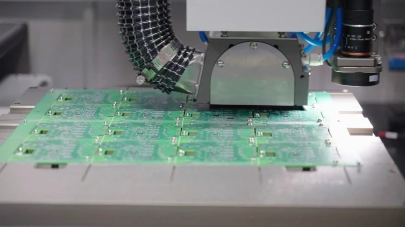
Router-bit depaneling addresses a fundamental limitation of V-scoring: it cannot handle boards with components mounted close to the depaneling route. A router machine uses a rotating bit — typically 1.0 to 3.175 mm diameter — spinning at 40,000 to 80,000 RPM to cut along a programmed path between individual boards. The board is held in place by a vacuum chuck, and the routing tool follows XY coordinates with a positional accuracy of ±0.03 mm. Feed rates are determined by the bit diameter, the number of flutes, and the board material — FR-4 laminates typically route at 1.5–3.0 mm/s per spindle revolution, while flex boards require significantly slower rates to avoid delamination. The cutting stress on a router-depaneled board measures substantially lower than mechanically broken boards, typically below 200 microstrain, which is well within the elastic deformation range for standard PCB substrates. IPC-A-600H Class 3 requirements specify that the routed edge must be free of burrs exceeding 0.13 mm in height and that no delamination or measling occurs within 0.5 mm of the cut edge.
Punch-Die and Laser Methods
For production runs exceeding 10,000 units per shift, progressive punch-die tooling offers the fastest cycle time — typically 0.8 to 1.5 seconds per panel. The tooling die is custom-manufactured to match the board outline, with punch clearance of 0.02–0.04 mm per side on standard 1.6 mm boards. The primary risk with punch-die depaneling is compression damage to nearby components if they fall within 1.5 mm of the board edge. Laser depaneling, while more expensive per unit, eliminates all mechanical force entirely. A CO2 or UV laser with a wavelength matched to the substrate’s absorption profile vaporizes material along the depaneling path. The kerf width with UV lasers can be controlled to 0.05–0.10 mm, making it suitable for fine-pitch boards where mechanical clearance is minimal. The heat-affected zone (HAZ) with modern short-pulse lasers remains below 0.15 mm, far less than the thermal damage seen with early continuous-wave laser systems.
Stress Management and Fixture Design
Regardless of the separation method, board stress during depaneling is the dominant failure driver. The depaneling fixture must provide uniform support across the panel while allowing the separation mechanism to act with minimal transferred torque. Best-practice fixture design positions vacuum hold-down points at a minimum of 5 mm from the depaneling route, and uses independent zoned vacuum to compensate for panel bow that occurs after reflow soldering. The board support stiffness should match or exceed 500 N/mm to prevent downward flex during separation — insufficient stiffness directly correlates with S-shaped curl and subsequent pad cratering near the depaneling edge. Stress gauges or strain rosettes should be used during process qualification to confirm that residual strain at the outermost component remains below the 800 microstrain threshold specified in IPC-2221 for interconnections.
Process Validation and Ongoing Monitoring
A depaneling process qualified once and left unmonitored will drift. The primary variables that degrade over time are blade wear (for router and V-scoring) and die clearance changes from tooling deflection during high-volume runs. Blade wear monitoring can be automated through spindle current draw — a 15–20% increase in current at constant feed rate indicates measurable wear. Production tooling should be inspected every 8 hours for punch clearance changes and router bit diameter reduction exceeding 0.02 mm. Statistical process control charts tracking depaneling-related field failures should target a rate below 50 parts per million for Class 3 applications. Every depaneling method carries a specific stress signature that can be characterized with digital image correlation or thermography during process development — this characterization data becomes the baseline for detecting drift during production.
The depaneling operation is not a trivial post-process step. It is a precision separation operation where the board’s mechanical integrity, the reliability of every nearby solder joint, and the longevity of copper interconnections are all determined by force control, positional accuracy, and tooling maintenance. Selecting the correct method — router, V-score, punch, or laser — requires evaluating the component proximity to the depaneling route, the production volume, the substrate material, and the applicable IPC class requirements. Only when these factors are matched to the process parameters with disciplined control will the separated board meet the reliability standards demanded by modern electronic assemblies.
Recommended Equipment
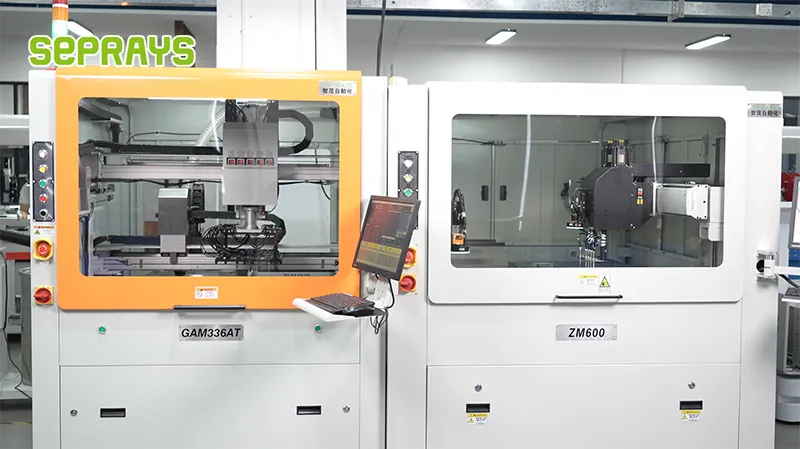
Looking for proven depaneling solutions? Seprays offers a full range of equipment backed by 30+ years of industry experience. Here are two options worth considering for your production line:
- GAM310A Offline Automatic Board Separator — Compact single workbench with CCD visual correction — high precision in a small footprint
- GAM330AT Fully Automatic PCB Depaneling Machine — Self-feeding operation with automatic sorting — ideal for high-volume automated production lines
Frequently Asked Questions
Q1: What spindle speed is used in PCB depaneling routing, and why does it matter?
A1: PCB depaneling routers typically operate at spindle speeds of 60,000 to 100,000 RPM, driven by high-frequency motors. This high rotational speed enables the router bit to cut smoothly through FR-4, CEM-1, CEM-3, and polyimide substrates without causing delamination, stress cracks, or thermal damage to copper traces. The combination of appropriate RPM and controlled downward feed force is what separates precision routing from manual separation methods.
Q2: How does the depaneling programming system work when setting up a new board profile?
A2: The system uses a teaching pendant or on-screen editor to input the XY coordinates of each depaneling segment, followed by a Z-axis height calibration pass that measures the board surface elevation. Once the cutting path and penetration depth are confirmed through a test run, the complete program is stored and recalled for production, eliminating repeated setup time across board runs. This CAD-based approach provides repeatability down to ±0.05mm positioning accuracy.
Q3: What types of stress-related defects does a depaneling router eliminate compared to manual breaking or punching?
A3: Manual separation methods generate significant bending and shear stress at the panel edges, which frequently causes micro-cracks in the substrate, copper trace lifting, and internal delamination — defects that may not appear until field failure. In contrast, a depaneling router achieves separation through controlled milling, where the rotating bit progressively cuts along the V-score line, converting the separation force into low-stress material removal. This method consistently meets IPC-A-600 cleanliness standards for edge quality and minimizes latent reliability failures.
About Seprays
About Seprays Precision Machinery
Founded in 1993, Seprays has over 30 years of expertise in PCB depaneling solutions. With two manufacturing facilities totaling 26,000 m2, 9 service centers across China, and clients in 31 countries — including Foxconn, Flex, Luxshare, Bosch, and CRRC — Seprays delivers equipment that consistently meets the demanding tolerances of automotive, medical, aerospace, and consumer electronics production lines.
Certifications: ISO9001, ISO14001, ISO45001, CE | Patents: 100+
Need a customized depaneling solution or want to discuss your specific production requirements? Our technical team is ready to help.
Contact: jimmy@seprays.com