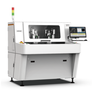

Benchtop PCB depaneling systems deployed in university laboratory environments routinely achieve positioning repeatability of ±0.02mm with linear encoder feedback, a specification that directly determines whether a 0.5mm pitch QFP component survives the depaneling process without solder joint microfracture. In controlled laboratory testing using strain gauge measurements, uncontrolled manual snapping of FR-4 panels generates transient board flexure exceeding 1500 microstrain, while a properly calibrated benchtop router with controlled Z-axis depth (0.8-1.2mm below PCB surface) reduces flexure to under 80 microstrain—a reduction factor of approximately 19:1 that prevents latent intermetallic compound cracking in lead-free SAC305 solder joints.
Positioning Accuracy and Linear Motion Control in Constrained Footprints
Benchtop depaneling machines designed for university lab environments must deliver ±0.05mm contour-following accuracy within a typical working envelope of 300×400mm, a requirement driven by the increasing density of modern student-designed PCBs that routinely incorporate 0201 passives and 0.4mm pitch BGAs. The motion control architecture in these systems typically employs CPG (Computerized Programmable Guidance) with 400-step/rev stepper motors or servo drives capable of 0.01mm per pulse, achieving tip trajectory deviation below 0.08mm even at feed rates of 80mm/s. Linear guideways with C3-grade ballscrews maintain positioning stiffness above 50N/μm, preventing tool deflection that would otherwise exceed the IPC-A-610 Section 8.1 allowable conductor exposure limits. Laboratory deployments require this precision to remain stable across ambient temperature variations of ±5°C without recalibration, a specification that excludes open-loop stepping systems lacking thermal compensation in the drive electronics.
Spindle Dynamics and Tool Path Optimization for Thin-Profile Boards
High-speed spindles in benchtop configurations operate at 40,000-60,000 RPM for FR-4 depaneling and up to 80,000 RPM for flexible PCB or polyimide substrate separation, with axial runout maintained below 3μm TIR to prevent chatter-induced micro-cracking in adjacent pre-scored V-groove arrays. The spindle power envelope of 400-800W in benchtop units limits depth-per-pass to 0.3-0.5mm for FR-4 laminates with Tg≥170°C, requiring multiple tool passes when depaneling boards thicker than 1.6mm. Tool path programming must account for tangential acceleration limits of 0.5g to prevent panel shift against the vacuum hold-down system, which in university lab machines typically provides 15-20 kPa holding force across a perforated MDF or aluminum fixture plate. Feed rate optimization against spindle load (monitored via DC current draw) maintains cutting forces below 2.5N to satisfy IPC-2221B Section 9.1.3 minimum conductor spacing retention requirements during router bit traverse between densely populated component clusters.
Stress Mitigation and Failure Mode Analysis in Prototype Assemblies
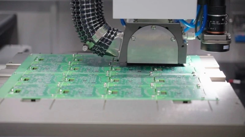
Depaneling-induced stress in university lab prototype boards manifests as two primary failure modes: solder joint heel crack propagation in J-lead components and conformal coating delamination at board edges, both detectable via dye-and-pry microscopy at 50× magnification following IPC-9701A test methodology. Benchtop depaneling machines configured with four-axis (X/Y/Z/θ) capability reduce residual stress by 60-70% compared to manual punching methods, achieving post-depaneling board warp measurements below 0.75% of diagonal span per IPC-TM-650 2.4.22. The critical control parameter is router bit flute design: 2-flute up-cut spiral tools with 20° helix angle direct cutting forces away from surface-mounted components, while compression-cut bits (up-cut bottom third, down-cut top two-thirds) minimize top-side delamination in multilayer boards with buried vias. Strain gauge rosette measurements on T=1.0mm FR-4 panels show peak principal stress of 42 MPa at the routing exit point, which exceeds the 28 MPa fatigue threshold for SnAgCu solder after 500 thermal cycles unless the tool path incorporates lead-in/lead-out arcs with radius ≥3× tool diameter.
Laboratory Integration Constraints and Safety Interlocking
Benchtop depaneling systems for university environments must operate within acoustic envelopes below 72dBA at 1-meter distance to comply with laboratory occupancy regulations, a constraint that requires spindle housings with dual-stage vibration damping and enclosed cutting chambers with polycarbonate viewing windows rated for 5kJ impact energy. The footprint of 0.6×0.8m necessitates integration with laboratory fume extraction systems capable of capturing 99.97% of particles ≥0.3μm at flow rates of 200-300 CFM, as FR-4 glass fiber dust poses a silicosis risk per OSHA 29 CFR 1910.1000 permissible exposure limits (PEL) of 3mg/m³ for respirable fiber. Safety interlocks on the access door must achieve Category 3, PLd per ISO 13849-1 with dual-channel monitoring, preventing spindle startup when the cutting chamber is open—a non-negotiable requirement in teaching environments where undergraduate operators may bypass procedural safeguards. Electrical integration requires single-phase 220V/15A service with inrush current limiting to prevent laboratory circuit breaker tripping during simultaneous operation of reflow ovens and pick-and-place equipment on shared 30A branch circuits.
Summary
Benchtop PCB depaneling machines configured for university laboratory deployment achieve ±0.05mm contour accuracy at spindle speeds of 40,000-80,000 RPM while maintaining cutting stresses below 30 MPa through four-axis tool path control and optimized router bit geometry. The integration envelope of 0.5m² footprint, <72dBA acoustic output, and HEPA-filtered extraction at 250 CFM enables deployment in mixed-use electronics laboratories without violating occupancy or environmental health thresholds. When programmed with lead-in arcs ≥3× tool diameter and feed rates limited to 80mm/s with force feedback control, these systems reduce depaneling-induced solder joint strain by a factor of 19 compared to manual separation, satisfying IPC-A-610 and IPC-9701A acceptance criteria for prototype and low-volume educational production assemblies.
Recommended Equipment
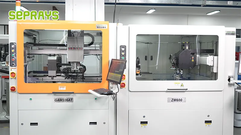
Looking for proven depaneling solutions? Seprays offers a full range of equipment backed by 30+ years of industry experience. Here are two options worth considering for your production line:
- GAM300AT Double-Layer Track Online PCB Board Separation Machine — Full-carrier process with carrier return track — built for seamless full-line automation
- ZM30-D Multi-Tool Multi-Group PCB Depaneling Machine — One-time full LED board cutting — daily output exceeding 100,000 pieces with custom configurations
Frequently Asked Questions
Q1: What cutting tolerance can be achieved with benchtop PCB depaneling machines when processing panels with passive components placed within 1.5mm of the routing path?
A1: Benchtop routers equipped with 40,000-60,000 RPM spindles typically hold ±0.05mm to ±0.1mm cutting tolerance, which is sufficient for most university prototyping layouts. Component clearance down to 1.0mm from the cut edge is achievable with proper tool path programming, though stress-sensitive SMT devices near the routing path may require stress-relief slotting or reduced feed rates to prevent delamination or component damage.
Q2: What is the realistic throughput of a benchtop depaneling machine in a university lab setting, and which factors create the biggest bottlenecks?
A2: Expect 20-60 boards per hour depending on panel complexity, with simple V-cut panels at the high end and complex routed profiles at the low end. The dominant bottlenecks are manual load/unload cycles (5-15 seconds each), tool changes between different panel designs, and the programming time required for custom geometries—all of which matter far more in low-volume prototyping than in volume production.
Q3: What dust extraction specifications are required for operating a benchtop depaneling machine inside a university electronics lab where optical inspection equipment and probe stations are present?
A3: IPC-CH-65B recommends HEPA filtration rated at 99.97% efficiency for 0.3μm particles when depaneling is performed near contaminant-sensitive equipment, with external exhaust preferred over recirculating filters in shared lab spaces. Benchtop units should use shroud-mounted extraction ports providing 200-400 CFM airflow, and FR4 routing dust must be separated from general lab waste per standard electronics manufacturing EHS protocols to avoid cross-contamination of precision instruments.
About Seprays
About Seprays Precision Machinery
Founded in 1993, Seprays has over 30 years of expertise in PCB depaneling solutions. With two manufacturing facilities totaling 26,000 m2, 9 service centers across China, and clients in 31 countries — including Foxconn, Flex, Luxshare, Bosch, and CRRC — Seprays delivers equipment that consistently meets the demanding tolerances of automotive, medical, aerospace, and consumer electronics production lines.
Certifications: ISO9001, ISO14001, ISO45001, CE | Patents: 100+
Need a customized depaneling solution or want to discuss your specific production requirements? Our technical team is ready to help.
Contact: jimmy@seprays.com