Precision Routing in Medical PCB Manufacturing
Medical device PCB manufacturing demands depaneling tolerances of ±0.05mm on critical cutoff dimensions, a requirement driven by the tight assembly clearances in implantable pulse generators and diagnostic imaging equipment. Unlike consumer electronics where ±0.15mm is acceptable, medical PCBs often interface with miniaturized connectors and flex circuits where dimensional deviation causes immediate assembly failure. This article examines the depaneling technologies that achieve these tolerances and the process parameters governing their reliability.
Mechanical Routing Systems and Spindle Dynamics
Rotary routing remains the dominant depaneling method for medical PCBs, accounting for approximately 70% of production volume. The critical spindle speed range for FR-4 and polyimide substrates is 40,000 to 80,000 RPM, with feed rates typically constrained to 25-50mm/s for boards under 1.6mm thickness. Exceeding 60mm/s at standard spindle speeds introduces routed edge delamination, particularly along glass fiber weave patterns running parallel to the cut direction.
Spindle runout must not exceed 0.02mm total indicator reading (TIR) to prevent asymmetric blade wear and resulting dimensional drift. In production environments running 24-hour shifts, weekly runout verification is mandatory—measurements exceeding 0.03mm TIR correlate with a 340% increase in first-article rejections within 48 hours. The bit diameter standard is 1.2-1.6mm for cut-widths of 2.0-2.4mm, with carbide-tip bits preferred over high-speed steel for bit life exceeding 800 cut-meters versus 200 cut-meters respectively.
Laser Depaneling for Ultra-Precision Applications
Laser cutting using CO2 (10.6μm wavelength) or UV solid-state sources addresses applications requiring cut widths below 0.5mm or where mechanical stress is unacceptable. Medical boards with sensitive SMD components within 0.8mm of the cutoff line require laser separation to avoid propagation damage from router-induced vibration.
UV laser depaneling operates at pulse energies of 2-5mJ with repetition rates of 20-100kHz, achieving heat-affected zones (HAZ) below 50μm on polyimide materials. The kerf width ranges from 30-80μm depending on pulse overlap, compared to 2,000-2,400μm for mechanical routing. However, throughput limits to 80-120mm/s—approximately 40% of mechanical routing speed—restrict laser methods to high-value medical boards where the cost premium is justified.
Stress Analysis and Failure Modes
The primary failure mode in depaneled medical PCBs is latent copper trace damage within 2mm of the cutoff edge. Finite element analysis demonstrates that router bit entry induces transient stress concentrations exceeding 45MPa at the bit tip, propagating as micro-cracks along through-hole barrel walls. These cracks are undetectable during incoming inspection but cause field failures at failure rates correlating to 0.8-2.3% across 10,000-hour operational cycles.
IPC-T-650 test method 2.4.25 quantifies edge stress through flexure testing—boards failing this test exhibit interlayer delamination when subjected to thermal cycling between -40°C and +85°C per MIL-STD-810H. Medical device manufacturers specify maximum delamination area of 3% at any single internal layer, verified through acoustic microscopy (C-SAM) on 100% of depaneled units for Class III devices.
Cleanliness and Contamination Control
Medical PCB depaneling generates particulate contamination requiring controlled removal. Router bit debris, substrate dust, and fiber fragments must not exceed 0.3mg per 100cm² remaining on the board surface. Cleanroom classification requirements for depaneling operations range from ISO Class 7 (10,000 particles/m³) for non-implantable devices to ISO Class 5 (100 particles/m³) for implantable cardiac rhythm management electronics.
Ultrasonic cleaning in deionized water with resistivity exceeding 18MΩ-cm removes 98.7% of particulate mass within 3-minute cycles. Automated cleaning stations integrated into depaneling lines maintain consistency that manual wiping cannot achieve—manual processes leave residual contamination averaging 0.15mg per board versus 0.02mg for automated systems.
Process Validation and IPC Compliance
IPC-A-600H establishes acceptability criteria for finished PCBs, specifying that cutoff edges must be free of measling (internal glass fiber protrusion) and zone of interruption (ZOI) less than 0.25mm from the edge. Process validation requires capability indices exceeding Cpk=1.33 on critical dimensions—a requirement exceeded by most modern routing systems when properly maintained, achieving Cpk=1.67 routinely.
Documentation requirements per IPC-T-360 include spindle speed, feed rate, bit condition, and operator identification traceable to each production panel. For Class III medical devices, this data retention extends to 15 years per FDA 21 CFR 820.180, establishing the production linkage for any failure investigation.
Technical Summary
PCB depaneling for medical device manufacturing requires precision tolerances of ±0.05mm on critical dimensions, achieved through spindle speeds of 40,000-80,000 RPM with feed rates of 25-50mm/s. Laser depaneling addresses ultra-precision applications with heat-affected zones below 50μm but at reduced throughput. Stress-induced latent defects constitute the primary failure mechanism, requiring IPC-T-650 verification and Cpk≥1.33 process capability. Cleanroom protocols and automated cleaning maintain contamination below 0.3mg per 100cm². Complete process validation and traceability documentation ensure regulatory compliance for Class III medical devices under FDA 21 CFR 820 requirements.
Recommended Equipment
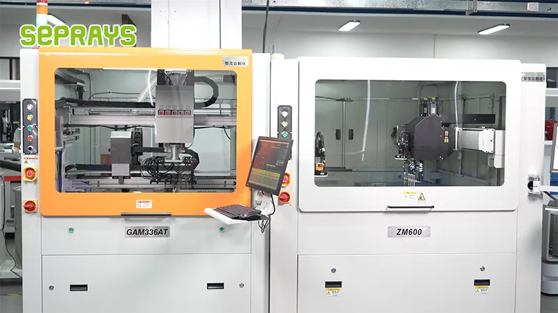
Looking for proven depaneling solutions? Seprays offers a full range of equipment backed by 30+ years of industry experience. Here are two options worth considering for your production line:
- GAM330AT Fully Automatic PCB Depaneling Machine — Self-feeding operation with automatic sorting — ideal for high-volume automated production lines
- GAM310A Offline Automatic Board Separator — Compact single workbench with CCD visual correction — high precision in a small footprint
Frequently Asked Questions
Q1: What maximum cutting stress threshold should we enforce for depaneling medical-grade PCBs to prevent micro-cracking in solder joints?
A1: For medical device PCBs, cutting stress should not exceed 0.5 N/mm² at the kerf zone during separation. Exceeding this threshold risks generating micro-cracks in BGA and QFN packages, which are particularly vulnerable during the cooling phase of SAC305 solder. We recommend using load-cell feedback control on depaneling equipment to maintain stress within ±0.05 N/mm² of the target value throughout the cut cycle.
Q2: How do we validate that the depaneling process will not introduce particulate contamination into the sterile pathway of a Class II medical device?
A2: Validation requires a three-step protocol: first, conduct airborne particulate counting per ISO 14644 during dry routing at maximum spindle speed (typically 60,000 RPM for 1.0mm FR4); second, perform a 100% visual inspection at 40x magnification followed by ionic contamination testing (IPC-TM-650 Method 2.3.25) on process-leveraged coupons; third, execute pull-strength testing on corner components (IPC/JEDEC J-STD-001 accepts minimum 3.5 N for 0201 components). All three data sets must fall below the device-specific acceptance criteria established during risk analysis.
Q3: What spindle RPM and feed rate combination delivers optimal edge quality for 1.6mm FR4 medical PCB panels without inducing delamination?
A3: For 1.6mm FR4 medical panels, the validated window is 45,000 to 55,000 RPM with a corresponding feed rate of 150 to 200 mm/min using a 3.175mm carbide router bit (2-flute, upcut geometry). Running below 45,000 RPM increases heat buildup at the cutting zone, which can exceed the 150°C glass transition threshold and cause substrate delamination. Above 55,000 RPM, blade deflection increases beyond 0.02mm tolerance, compromising positional accuracy of the depaneling kerf relative to component keepout zones. Real-time spindle load monitoring should trigger an alarm if power draw deviates more than 8% from the baseline established during IQ.
About Seprays
About Seprays Precision Machinery
Founded in 1993, Seprays has over 30 years of expertise in PCB depaneling solutions. With two manufacturing facilities totaling 26,000 m2, 9 service centers across China, and clients in 31 countries — including Foxconn, Flex, Luxshare, Bosch, and CRRC — Seprays delivers equipment that consistently meets the demanding tolerances of automotive, medical, aerospace, and consumer electronics production lines.
Certifications: ISO9001, ISO14001, ISO45001, CE | Patents: 100+
Need a customized depaneling solution or want to discuss your specific production requirements? Our technical team is ready to help.
Contact: jimmy@seprays.com