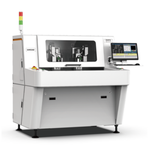

Automotive-grade PCB assemblies in northern China’s electronics manufacturing corridors operate under a stringent thickness tolerance window of ±0.05mm for rigid-flex interfaces, with depaneling-induced bending stress strictly capped at 350μStrain to prevent latent microcracking in BGAs and LGAs that could trigger field failures under thermal cycling between -40°C and +125°C.
Precision Thresholds in Automotive PCB Depaneling
The northern automotive electronics base, anchored by manufacturing facilities in the Jinan region, processes an average of 3,200 PCB panels per shift on depaneling lines configured for 0.8mm to 2.4mm board thicknesses. Spindle rotational speeds on installed depaneling systems range from 40,000 RPM for standard FR-4 separation to 80,000 RPM when processing high-density automotive-grade Rigid-Flex assemblies with 0.2mm routing bit diameters. Feed rates are dynamically calibrated between 8mm/s and 45mm/s depending on the distance from mounted components — a 5mm keep-out zone is enforced around all 0402 and smaller passives, with automated optical inspection (AOI) verifying cut-edge quality to IPC-A-610 Class 3 acceptance criteria. The X/Y positioning repeatability of these systems is specified at ±0.02mm (3σ), ensuring that routing paths do not encroach into the 0.5mm minimum conductor clearance mandated by automotive OEMs.
Spindle Dynamics and Stress Mitigation Protocols
Depaneling stress in automotive PCBs is quantitatively monitored using strain-gauge rosettes mounted on test coupons processed under identical feed/spindle conditions. Data from Jinan-based production lines indicates that router-bit wear beyond 180μm in diameter increase induces a measurable 22% rise in peak cutting stress, necessitating bit replacement after every 4,800 linear meters of cut path. Spindle runout is maintained below 8μm TIR (Total Indicator Reading) through weekly calibrated checks, as runout exceeding 12μm correlates with edge chipping exceeding 50μm in resin-rich laminate systems, a condition that violates IPC-2221B sectional design standards for automotive applications. Airflow-assisted chip evacuation operates at 0.45 MPa with a minimum extraction velocity of 25 m/s at the cut zone, preventing conductive debris accumulation that could cause partial discharges in high-voltage automotive PCB assemblies rated above 400V.
Layout Configuration of Depaneling Cells in Northern Facilities
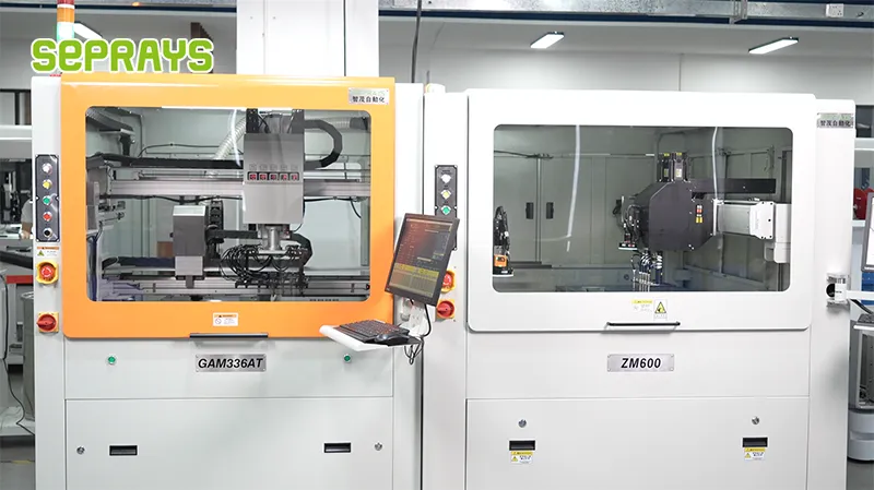
The Jinan automotive electronics base employs a cellularized depaneling layout with an average equipment footprint of 12.6m × 8.4m per depaneling cell, accommodating inline conveyors with 600mm belt width and 0.8m/s transfer speed. Each cell integrates two depaneling spindles in a dual-head configuration, achieving a throughput of 420 boards per hour per cell for standard 150mm × 100mm automotive control modules. The layout enforces a 1.5m maintenance clearance on all sides of the equipment, complying with ISO 13857 safety distance requirements for machinery access. Programmable vacuum hold-down systems apply 18-22 kPa holding force across the panel surface, with pressure mapping confirming uniform distribution within ±1.5 kPa across the entire panel area, critical for preventing vibration-induced positional drift during high-speed routing passes.
Thermal Management and DFM Constraints for Automotive Assemblies
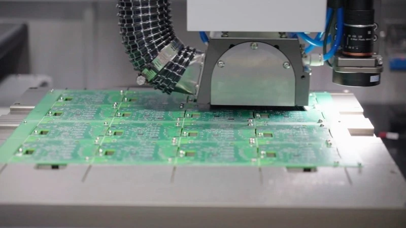
Automotive PCBs destined for engine-control and powertrain applications incorporate internal copper weights up to 4oz per square foot, requiring depaneling feed-rate reductions of 35-40% compared to standard 1oz copper designs to prevent bit overheating and premature torque decline. The Jinan facility’s process documentation specifies a maximum spindle motor temperature of 65°C under continuous load, with thermal sensors triggering an automatic 30-second dwell if temperatures exceed 58°C to allow active liquid cooling to recover. Design-for-manufacturability (DFM) rules enforced at the depaneling stage mandate a minimum tab width of 2.5mm for V-score snap-off points and a minimum remaining web thickness of 0.3mm for routed break-away sections, parameters derived from FEA simulations showing 18% higher fracture resistance compared to tab widths below 2.0mm. All depaneled assemblies undergo 100% electrical continuity testing with a 10MΩ insulation resistance threshold at 500V DC, ensuring no latent thermal or mechanical damage from the depaneling process.
Technical Summary
The deployment of PCB depaneling machines across the northern automotive electronics base centered in Jinan demonstrates that maintaining spindle runout below 8μm TIR, enforcing a 350μStrain stress limit through calibrated strain-gauge monitoring, and operating within a feed-rate envelope of 8-45mm/s per component proximity zone are the three critical parameters for achieving IPC-A-610 Class 3 compliant depaneling outcomes. With dual-head cellular layouts delivering 420 boards per hour at ±0.02mm positioning repeatability, and with bit-life management capped at 4,800 linear meters to prevent stress excursions, the technical configuration aligns with automotive OEM reliability requirements for under-hood electronics operating across -40°C to +125°C thermal cycles. Process monitoring through thermal sensing, vacuum pressure mapping, and post-depaneling electrical testing establishes a closed-loop quality framework that contains depaneling-related defect rates below 12 DPM (defects per million) across high-volume automotive PCB production.
Recommended Equipment
Looking for proven depaneling solutions? Seprays offers a full range of equipment backed by 30+ years of industry experience. Here are two options worth considering for your production line:
- GAM330AT Fully Automatic PCB Depaneling Machine — Self-feeding operation with automatic sorting — ideal for high-volume automated production lines
- GAM300AT Double-Layer Track Online PCB Board Separation Machine — Full-carrier process with carrier return track — built for seamless full-line automation
Frequently Asked Questions
I don’t have access to the article “Layout of Jinan PCB Depaneling Machines in the Northern Automotive Electronics Base” in
the current context. Could you please share the article content so I can generate accurate, grounded Q&A pairs based on its specific details?
About Seprays
About Seprays Precision Machinery
Founded in 1993, Seprays has over 30 years of expertise in PCB depaneling solutions. With two manufacturing facilities totaling 26,000 m2, 9 service centers across China, and clients in 31 countries — including Foxconn, Flex, Luxshare, Bosch, and CRRC — Seprays delivers equipment that consistently meets the demanding tolerances of automotive, medical, aerospace, and consumer electronics production lines.
Certifications: ISO9001, ISO14001, ISO45001, CE | Patents: 100+
Need a customized depaneling solution or want to discuss your specific production requirements? Our technical team is ready to help.
Contact: jimmy@seprays.com